
User Manual


Siemens Building Technologies CE1N2822E / 29.11.1998
Landis & Staefa Division 3/8
situations, suppression of hydraulic creep is activated.
It closes the valve for eight minutes. If, after the subsequent test openings, the limit val-
ues are adhered to, the valve will resume normal control operation.
The heat energy consumption values are stored in non-volatile memory. In connection
with the central unit, the following data also become available:
–
Heat consumption on the set day
–
Monthly heat consumption values
In the event of a power failure, the valve can be operated manually. For this purpose,
the seal must be broken.
To prevent the valve from seizing after longer off periods, it is briefly opened and shut
again after no more than 200 hours.
Any meter with a pulse interface (e.g. gas, water or electricity meter) can be connected
to the control and heating cost allocation valve. The connection is made via the ALW30
conduit box. The meter's pulses are converted into consumption data and then stored
like energy consumption data (actual value, set day value, and monthly values).
Incoming pulses are shown on the display.
For additional meters, pulse adapter AEW2.1 is required. It has the same storage capa-
bilities as the control and heating cost allocation valve.
The WRV82... monitors itself and is able to detect errors and malfunctions. They are
handled as follows:
–
Display of the respective error code on the display
–
Signalling via the building bus to the central unit OZW30 and display of the respective
error code on the central unit's display
The central unit stores the last 50 fault status signals.
If the current flow rate exceeds the adjusted design value, the valve will limit the flow
rate (dynamic balancing). Flow rate limitation has priority over room temperature control.
This function can be deactivated.
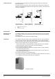
The control and heating cost allocation valve WRV82... consists of electronics, actuator
and valve. All components are accommodated in a housing made of die-cast zinc.
Due to its compact design, the WRV82... can be mounted in the apartment's cabinet or
in the installation trunk.
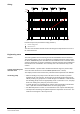
At the top of the valve, there is a 7-digit display:
Display for 10 seconds:
Meter reading of proportional amount of heat energy the
drawn from system
Display for 5 seconds:
Two-digit check number and flow rate in l/h
The check number is coded and generated from the displayed value. It permits the
reading to be verified. The check number is useful when doing the reading directly on
the unit, for communication to the billing agency.
If errors or faults occur, an appropriate error code will be displayed.
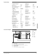
At the side of the valve, there is a socket for an address plug and a service interface.
With the address plug, a number is assigned to the control and heating cost allocation
valve when commissioning the plant.
The service interface is required for connecting the service unit AZW30.
Storage
Manual operation
Valve kick
Handling of pulses
from non-SYNERGYR
meters
Self-supervision
Limitation of flow rate
Mechanical design
Display
Parameter settings
and addressing