
User Manual


CE1N2822E / 29.11.1998 Siemens Building Technologies
2/8 Landis & Staefa Division
Description Type reference
Control and heating cost allocation valve
Nominal flow rate 200 l/h
Nominal flow rate 400 l/h
Nominal flow rate 750 l/h
Nominal flow rate 1500 l/h
WRV82.200
WRV82.400
WRV82.750
WRV82.1500
Mounting kit
ALG82
Conduit box for WRV82...
ALW30
Set of address plugs for address numbers 1...16
PTG1.16
Set of address plugs for address numbers 1...32
PTG1.32
Set of address plugs for address numbers 33...64
PTG1.64
Set of address plugs for address numbers 65...96
PTG1.96
Set of address plugs for address numbers 97...128
PTG1.128
When ordering, please give type reference of the control and heating cost allocation
valve according to “Type summary“.
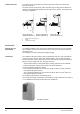
The initial delivery during the construction phase includes conduit box ALW30 and
mounting kit ALG82. The WRV82... along with the address plugs should only be deliv-
ered prior to commissioning. For details, please contact Landis & Staefa.
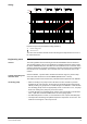
Each apartment requires:
–
One control and heating cost allocation valve
WRV82...
–
A maximum of two pulse adapters
AEW2.1
–
One room unit
QAW...
(QAW10 or QAW20)
For acquisition of the zone's flow temperature, each zone requires:
–
One temperature measuring unit
QAB30
(incl. immersion sensor)
For more information about the system structure, refer to data sheet 2801 and the data
sheets of the individual units.
The control and heating cost allocation valve features a two-position controller providing
control similar to PID.
In the reference room, the QAW... room unit acquires the room temperature and passes
it on to the controller integrated in the WRV82.... In the other rooms, room temperature
control is ensured by thermostatic radiator valves.
To determine the amount of thermal energy consumed, the control and heating cost
allocation valve is supplied
–
the zone's flow temperature via the building bus
–
the return temperature.
For this purpose, it acquires the auxiliary measuring variable "pressure drop" across the
valve. This is used to determine the flow rate and the proportional amount of energy
drawn from the system.
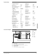
The flow rate is determined based on the effective pressure principle. For this purpose,
the valve features an orifice, a two-stage valve plug and a diaphragm measuring sys-
tem. The two-stage valve plug is used to change the measurement range in function of
the effective pressure.
If the flow rate or the temperature differential falls below the respective low limit value,
the actual heat demand of the apartment has dropped below the acquisition limit of the
control and heating cost allocation valve. To maintain the guaranteed error limits in such
Type summary
Ordering
Equipment
combinations
Technical design
Room temperature
control
Determination of thermal
energy consumption
Measurement of thermal
energy consumption
Suppression of
hydraulic creep