SAMMS-MV ™ Siemens Advanced Motor Master System for Medium Voltage Motors User's Manual 11 12 13 14 15 16 1 2 3 4 5 6 7 8 9 10 Manual No.
IMPORTANT The information contained herein is general in nature and not intended for specific application purposes. It does not relieve the user of responsibility to use sound practices in application, installation, operation, and maintenance of the equipment purchased. Siemens reserves the right to make changes in the specifications shown herein or to make improvements at any time without notice or obligations.
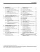
Contents 1 Introduction ............................................. 2 3.9 1.1 1.2 About About 1.2.1 1.2.2 3.10 3.11 3.12 this Manual ............................................ 3 the SAMMS-MV Device.......................... 3 The SAMMS-MV Device Models ............ 4 Advanced Protection for Medium-Voltage Motors ................................................... 4 1.2.3 Overload Protection ............................... 5 1.2.4 Programming Control Circuits ................ 5 1.2.
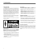
1 Introduction 1 Introduction The SAMMS-MV electronic motor control and protection device is designed and manufactured in accordance with the latest applicable provisions of the National Electric Code, Underwriters Laboratories Standards and Procedures, NEMA Standards, and the National Electric Safety Code. You must thoroughly read and understand this users manual before you begin any work with the SAMMS-MV device.
1 Introduction 1.1 About this Manual 1.2 About the SAMMS-MV Device This manual introduces you to the Siemens Advanced Motor Master System (SAMMS-MV) motor protection and control relay which incorporates protection designed for medium voltage machines. This manual also contains information for installing and operating the device, communicating with other devices over the ACCESS electrical distribution communications system, and troubleshooting the device.
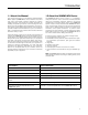
1 Introduction 11 12 13 14 15 16 1 2 3 4 5 6 7 8 9 10 Figure 1.1 SAMMS-MV, front view 1.2.1 The SAMMS-MV Device Models The SAMMS-MV device is available in two models: SAMMS-MVE and SAMMS-MVX. Each model meets the various demands of industrial and commercial specifications and installations. Table 1.2 compares the features of each model. The SAMMS-MV device is designed for critical process control where prevention of downtime is critical.
1 Introduction across-the-line starters to complicated reduced-voltage starters. With optional software, the specified control circuit can be loaded either from the library or from a modified version into the microprocessors memory, in the factory or on site, using an IBM®-PC compatible computer. If you would like to learn more about this software package, refer to SAMMS Custom Software Manual, Bulletin CP 3291.
1 Introduction SAMMS-MV Model SAMMS-MVE SAMMS-MVX X X Application Across-the-line (FVNR) Reversing X Two-speed X Reduced voltage X F0-F21 plus F25-F27 (except no F3, F5, or F8) F0-F27 Ridethrough upon loss of power No Yes Ground fault protection/alarm Yes Yes Programmable alarm contact No Yes Seven (preloaded), selectable with HHC.
2 Installing the SAMMS-MV Device 2 Installing the SAMMS-MV Device This section provides instructions for installing the SAMMS-MV device. You should adapt these instructions to suit the needs of your installation and equipment. 2.1 Receiving and Storing the SAMMS-MV Device Thoroughly inspect the equipment before accepting the shipment from the transportation company. Compare each item received against the packing list and report any shortages or damaged equipment to the carrier.
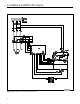
2 Installing the SAMMS-MV Device Figure 2.
2 Installing the SAMMS-MV Device Connect a ground bus to the chassis of each controller or to the chassis of the mounting equipment containing the earth ground through a grounding conductor. 2.4.2 Grounding the Device As stated in Guideline 5, ground each motor controller at a single ground point. The grounding path to earth must be permanent and continuous. It must also be able to safely conduct ground fault currents that may occur in the system to ground through minimum impedance.
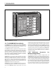
2 Installing the SAMMS-MV Device enables the SAMMS-MV to communicate with a remote supervisory device. Examples of the remote supervisory device include the Power Monitor display and monitoring unit, a standard personal computer running the Power Monitor PC communications and supervisory software, or Siemens Microsoft® Windows™ based SIEServe™ or WinPM™ software.
3 Operating the SAMMS-MV Device 3 Operating the SAMMS-MV Device This section explains how to operate the SAMMS-MV device. 3.1 Password Protection Changing the settings of the SAMMS-MV device requires the use of the Hand-Held Communicator (HHC) in the program mode. To access the program mode, the user needs a password. The SAMMS-MV device is shipped from the factory with the password 0000. This password can be changed by the user as described in section 3.29.1.
3 Operating the SAMMS-MV Device 3.4 Output Devices Front Panel Pushbuttons You can use the following SAMMS-MV output devices: AC Outputs The SAMMS-MVX device provides up to three AC coil drivers capable of driving contactors up to size H6, while SAMMS-MVE provides one coil driver. Control Relays The device provides up to eight software-controlled relays. These relays are helpful in local two-wire and other applications requiring maintained contacts.
3 Operating the SAMMS-MV Device The communications inputs must be included in the ladder logic (control circuit). 3.6 Ladder Diagrams 3.6.1 Library of Standard Ladder Diagrams The SAMMS-MV library of more than 40 ladder diagrams covers most standard motor control applications. Table 3.3 lists the standard control circuits and the input and output assignments for the library.
3 Operating the SAMMS-MV Device Figure 3.
3 Operating the SAMMS-MV Device Input Assignments Preloaded in SAMMS-MVE can be downloaded in SAMMS-MVX Available with SAMMS-MVX only Starter Type FVNR Program Block PB10 Control Type PB1 PB2 PB3 LOCAL, 2-WIRE OFF ON FVNR PB11 LOCAL, 3-WIRE STOP START FVNR PB12 LOCAL, 3-WIRE, REMOTE 2-WIRE STOP START FVNR PB13 LOCAL/REMOTE 2-WIRE STOP FVNR PB14 LOCAL/REMOTE 3-WIRE STOP START FVNR PB15 REMOTE, 2-WIRE FVNR PB16 REMOTE, 3-WIRE FVR PB17 LOCAL, 2-WIRE OFF FWD REV FVR
3 Operating the SAMMS-MV Device Input Assignments Available with SAMMS-MVX only Starter Type Program Block Control Type 2SPD, 1W, CH PB39 LOCAL, 2-WIRE OFF LOW HIGH 2SPD, 1W, CH PB40 LOCAL, 3-WIRE STOP LOW HIGH 2SPD, 1W, CH PB41 LOCAL, 3-WIRE, REMOTE 2-WIRE STOP LOW HIGH HAND OFF AUTO 2SPD, 1W, CH PB42 LOCAL/REMOTE 2-WIRE STOP LOW HIGH HAND OFF AUTO 2SPD, 1W, CH PB43 LOCAL/REMOTE 3-WIRE STOP LOW HIGH 2SPD, 1W, CH PB44 REMOTE, 2-WIRE 2SPD, 1W, CH PB45 REMOTE, 3-
3 Operating the SAMMS-MV Device 3.7 Incomplete Sequence Sometimes the motor contactors do not respond in a timely manner to start, stop, transition, speed or direction change commands from the controller. If the SAMMS-MV device does not detect motor current one second after issuing a start command or if the SAMMS-MV device detects motor current one second after issuing a stop command, an Incomplete Sequence trip occurs. The motor contactors are opened and the Incomplete Sequence LED illuminates solidly.
3 Operating the SAMMS-MV Device Figure 3.
3 Operating the SAMMS-MV Device Figure 3.6 Rotor and winding temperature during 10 second motor stall temperature. You can select ambient temperature from 0° to 70°C in increments of 5°C, with HHC function F0. are designed to cause a trip in 90% to 100% of the class time for a current of 600% of IFLC. Important: Do not use this feature with motors rated for ambient temperature other than the standard 40°C.
20 SECONDS 1 I ratio IFLC 10 Figure 3.7 Time-current characteristic curve for cold motors with SF=1.00 .1 1 10 100 1000 10000 SECONDS 1 I ratio IFLC 10 Figure 3.8 Time-current characteristic curve for warm motors with SF=1.00 .
.1 1 10 100 1000 1 IFLC I ratio 10 Figure 3.9 Time-current characteristic curve for cold motors with SF=1.15 SECONDS 10000 SECONDS 1 IFLC I ratio 10 Figure 3.10 Time-current characteristic curve for warm motors with SF=1.15 .
3 Operating the SAMMS-MV Device 100000 Motor running current at full load current 10000 Loss of load adjustable from 20 to 90% of rated FLC Jam protection adjustable from 120 to 400% of FLC Seconds 1000 Cold stall time adjustable from 5 to 100 seconds Class 5 curve 100 Jam and loss of load protection persistence delay (5 times overload class) 10 1 Motor starting current 600% rated full load current .1 .1 1 6 I ratio IFLC Figure 3.
3 Operating the SAMMS-MV Device 3.13 Ultimate Trip Level and Service Factor enable jam protection using HHC function F23. The ultimate trip level is the maximum continuous current that does not cause an overload trip. Any higher current applied indefinitely to an unprotected motor will ultimately damage it. The ultimate trip level for motors with a unity service factor is 110% of the full-load current setting. For motors with a service factor of 1.15, the ultimate trip level is 120%.
3 Operating the SAMMS-MV Device ture of the rotor and provides a signal to trip the motor off-line when it reaches a trip temperature value. The motor model takes into account the change of the rotor resistance during motor startup. Rotor resistance is a function of motor slip; therefore, it is highest at locked rotor and decreases as the motor speeds, and the slip decreases. You can select motor cold stall time from 5 to 100 seconds in increments of 1 second.
3 Operating the SAMMS-MV Device Figure 3.
3 Operating the SAMMS-MV Device Size Pickup Current Range Default Pickup Current H3A 7A to I FLC 10A H3B 7A to I FLC 10A H3C 7A to I FLC 10A H6 7A to I FLC 20A Table 3.6 Ground fault pickup levels Ground fault detection requires no additional external circuitry or transformers. Ground fault detection for the SAMMS-MV device is not available for grounded, three-phase systems or single-phase applications. Ground fault pickup time is 360 msec.
3 Operating the SAMMS-MV Device SAMMS-MV Function Number Function SAMMS-MVX SAMMS-MVE F0 Ambient temperature • • F1 Control circuit number • • F2 Size for overload No. 1 • • F3 Size for overload No. 2 (low speed) • F4 Full load current for OLR No. 1 • • F4A 5A CT primary current (if used) • • F5 Full load current for OLR No.
3 Operating the SAMMS-MV Device function. Pressing the LIST key returns the active setting to the display. press the (F)unction key. The display shows the number of the function most recently selected, (e.g. F9). There is one occasion when the LIST key is disabled making the corresponding functions inoperative. In a SAMMS-MV device with autoreset disabled at the factory, the LIST key has no effect for F8. 2. Use the UP or DOWN key (as described above) to step or scroll to the desired function.
3 Operating the SAMMS-MV Device Function Number Function Description Range Step Size Default Value F0 Select ambient temperature. 0 - 70º C 5º C 40º C F1 Display (or change for SAMMS-MVE) the control circuit number, Enable/disable incomplete sequence status. 0 - 9999 1 N/A F2 Display the size for single-speed controller, or the high-speed size for two-speed motor controllers. H3A, H3B, H3C, H6 As shown N/A F3 Display the low-speed size for two-speed controller.
3 Operating the SAMMS-MV Device Function Number F12 Function Description Range Step Size Default Value ON/OFF N/A OFF 7A-I FLC 1A F13 Select ground fault protection or warning. ON means protection; OFF means warning. Select ground fault pick-up current value. Set programmable timer #1. OFF - 200 seconds 1 second 10A (H3A-H3C) 20A (H6) OFF F14 Set programmable timer #2. OFF - 200 seconds 1 second OFF F15 Display the average line current and the H3A: 0 - 720A individual line currents.
3 Operating the SAMMS-MV Device Press and hold F key F UP DOWN Display mode Program mode ENTER ENTER Prompt for password UP UP To select function for viewing DOWN DOWN To select digit ENTER To enter digit ENTER First digit selected Enter following digits in the same manner 0000-9999 To change password ENTER No Password Correct? DOWN Yes Prompt for new password UP UP DOWN To select digit ENTER To enter digit First digit selected Enter new password twice No ENTER Authorized t
3 Operating the SAMMS-MV Device 3.29.1 Program Mode/Passwords To access the functions in program mode, the user is required to enter a password. The default password is 0000, and may be changed at any time. To enter the password and have access to program mode: 1. Press and hold the (F)unction key for several seconds until dISP is displayed. 2. Press the UP or DOWN key to change to the program mode. The display reads Prog . 3.
3 Operating the SAMMS-MV Device 5. To exit the program mode, press and hold the (F)unction key for several seconds. The display will show Prog . Press the UP or DOWN key to change to the display mode. F3 - Size for Overload Relay #2 (SAMMS-MVX Only) Overload relay #2 protects two-speed motors running on low speed. The possible values are H3A, H3B, H3C, H6 and OFF. OFF appears for single-speed motors. Use the following procedure to display the size for overload relay #2. 1.
3 Operating the SAMMS-MV Device 1. Press the LIST key to view the sensor in use for overload relay #2. If standard SAMMS sensors are used, the display will read OFF. If 5A secondary CTs are in use, the CT primary current will be displayed. 2. To change the setting, you must be in program mode. 3. Press the UP or DOWN key to scroll through the range of settings, until the selected setting appears on the display. 4. Press the ENTER key to change the active setting to the selected setting.
3 Operating the SAMMS-MV Device F8 - Autoreset (SAMMS-MVX Only) b. When phase unbalance protection is disabled (OFF), the Phase Unbalance LED remains off, unbalanced conditions have no effect on protection, and F17 (Display Unbalanced Current) displays OFF. 2. To change the setting, you must be in program mode. 3. To change the setting, press the UP or DOWN key to display the setting options, then press ENTER to select the setting that is shown. The display blanks while the ENTER key is pressed. 4.
3 Operating the SAMMS-MV Device your actions before pressing the ENTER key a second time to select the ON setting. 6. Repeat Step 3 if you select an incorrect setting. 7. If you are in the program mode, press and hold the (F)unction key for several seconds to exit. The display will show Prog. Press the UP or DOWN key to change to the display mode. 8. Press the (F)unction key to go to other functions. F12 - Ground Fault Protection or Warning 1.
3 Operating the SAMMS-MV Device Note: The value can be reset to zero with F21. a. Because only four characters can display at a time, individual line currents of 1000 amps and above are displayed as three dashes following the phase designator, e.g., A - - -. 2. The UP, DOWN, and ENTER keys are disabled for this function. b. For sizes H3A, H3B, and H3C, the current is displayed to the nearest 1 amp. For size H6, currents are displayed to the nearest 2 amps. F19 - Number of Motor Starts 2.
3 Operating the SAMMS-MV Device F22 - Process Current Warning Level (SAMMS-MVX Only) 1. Press the LIST key to view the active process current level. The value represents the percentage of the full load current setting above which a motor current causes the External Trip LED to flash. The function is disabled for five times the class time after starting, or after a speed or direction change. The range of settings is in 1% increments from zero (OFF) through 100. The factory default is OFF. 2.
3 Operating the SAMMS-MV Device 2. The UP, DOWN, and ENTER keys are disabled for this function. 3. Press the (F)unction key to go to other functions. F26 - Baud Rate 1. Press the LIST key to view the active setting. Allowable settings are 2400, 4800, or 9600 baud. The factory default is 4800. 2. To change the setting, you must be in program mode. 3. Press the UP or DOWN key to scroll through the range of settings, until the selected setting appears on the display. 4.
4 Troubleshooting 4 Troubleshooting the SAMMS-MV Device This section discusses how to troubleshoot the SAMMS-MV device. The troubleshooting guide below lists basic errors that can occur while operating the SAMMS-MV device. Use the guide as necessary to solve error conditions as they arise. Do not attempt to solve any error condition that is not listed in the troubleshooting guide. Instead, contact your Siemens representative.
4 Troubleshooting Troubleshooting Error Condition Main Cause Incomplete Sequence Indicates the SAMMS-MV unit does not detect current one second after a start command, or it detects current one second after a stop command. Guide Remedy 1 . If the unit trips one second after start, verify that current transformer secondary input is present in the range of 100 mVAC to 3.54 VAC at terminals 1, 2, and 3 with reference to 4.
4 Troubleshooting Troubleshooting Guide Error Condition Main Cause Remedy CPU Fault Indicates a problem in the microprocessor or a low voltage condition. Verify voltage between terminals 5 and 6 is more than 10 VAC. If fault persists, call Siemens. Ground Fault Indicates the ground fault current exceeded the threshold. If ground fault protection was selected, the ground fault LED illuminates solidly and the motor stops.
Appendix A Technical Specifications Appendix A - Technical Specifications of the SAMMS-MV Device M o to r C o nt r o l S p ec i fi c at i o ns Inputs Six pushbuttons Four remote inputs Outputs SAMMS-MVX: Three coil drivers Three light bars One programmable alarm contact SAMMS-MVE: One coil driver Two light bars Diagnostic LEDs * * * * * * * * * * * * Current unbalance Impending trip Overload trip External trip Incomplete sequence Ground fault CPU fault Ready Light bar flashes (timer timing) Impending
Appendix A Technical Specifications O v e rl o a d S p e c i fi c a t io n s Overload classes Overload classes 2 through 23 with one second increments. Trip Characteristics Tripping time at 6 x I FLC = 95% of the overload class (±5%). Tripping time at 1.5 x I FLC within two minutes for warm conditions for all classes. Tripping threshold (1.1 ± 0.05) x IFLC for motors with 1.00 service factor, and (1.2 ± 0.05) x IFLC for motors with 1.15 service factor. Tripping time 20 minutes @1.
Appendix A Technical Specifications S t a t i s ti c a l D a t a Elapsed motor running time - x10 - Range: 0.0 to 6553 (65,536 hours) - Unit increments: 10 hours Number of motor starts - x10 - Range:0.0 to 6553 (65,536 hours) - Unit increments: 10 operations Number of overload trips - Range: 0 to 9999 - Increments: 1 trip Current display Overload Relay Size H3A H3B H3C H6 Current Increments 1A 1A 1A 2A A l a rm C o nt a c t s ( S A MM S - M V X O n ly ) Configuration - N.C. - N.O.
Appendix A Technical Specifications D im en si on s SAMMS-MV 6.25 inches W; 6.00 inches H; 2.125 inches D Handheld Communicator 3.15 inches W; 5.7 inches H; 1.37 inches D E nv ir on me nt s Operating temperature range -25º C to +70º C. Storage temperature -40º C to +85º C. Relative humidity 5 to 95% non-condensing. Altitude 6600 ft. Vibration 5 g's at a frequency range of 10 to 60 Hz. Electrostatic discharge No hardware failures at 15 kV at any point in the front of the unit.
Appendix A Technical Specifications Catalog Number SAM6 SAMMS-MV Model Number SAM6 - SAMMS-MVE SAM7 - SAMMS-MVX Configuration L1ALG0000 Control Type L - Local and/or Remote Control Alarm Contacts Configuration (SAMMS-MVX Only) 0 - None 1 - Normally Closed Contacts (N.C.) 2 - Normally Open Contacts (N.O.
Appendix A Technical Specifications SIDE FRONT 1 2 3 4 5 6 7 8 9 SAMMS-MVX LED Current Unbalance Impending Trip Overload Trip 6.
Appendix A Technical Specifications 4.25 3.50 0.375 .188 DIA (2X) FOR MOUNTING 1.00 0.50 RATING LABEL LOCATION #10 STUD WITH NUTS, WASHER, & LOCKWASHER (TYPICAL) 2.
Siemens Energy & Automation, Inc. Switchgear and Motor Control Division P.O. Box 29503 Raleigh, NC 27626-0503 Bulletin MVC-9108 (New) 2M 0394FP Printed in U.S.A. © 1994 Siemens Energy & Automation, Inc.