
Operating Instructions

Commissioning (settings/options in the actuator)
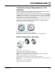
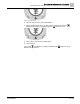
Mechanical position indicator (self-adjusting)
A6V12052002
57 | 80
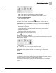
➥ The setting of the mechanical position indicator is correct, if the angle between the
symbols (OPEN) and (CLOSED) ranges between approx. 120° and 280°.
➥ If all three discs are turned at the same time, the indicator can be shifted in steps of
15°. Individual shifts of 5° are possible.
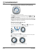
➥ If the indicator is rotated too far (more than 280°) or the angle too small (below
120°), adapt the turns/stroke of the actuator. See the <Gear stage of the reduction
gearing: test/set>.
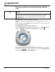
Gear stage of the reduction gearing: test/set
The test/setting is only required if the mechanical position indicator cannot be correctly
set.
See the table below and check if turns/stroke correspond to the setting of the
reduction gearing (stages 1– 9).
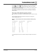
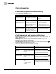
Table 19: Turns of actuator per valve stroke and suitable reduction gearing
setting.
for 1 – 500 turns/stroke
for 10 – 5,000 turns/stroke
Reduction gearing
[exceeding – to]
[exceeding – to]
Stage
1.0
– 1.9
10
– 19
1
1.9
– 3.7
19
– 37
2
3.7
– 7.9
37
– 79
3
7.9
– 15.0
79
– 150
4
15.0
– 31.5
150
–
315
5
31.5
– 60.0
315
–
600
6
60.0
– 126
600
–
1,260
7
126 – 240
1,250
– 2,500
8
240 – 500
2,500
– 5,000
9
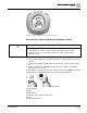
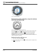
To modify settings, lift the lever at the reduction gearing and engage at the selected
stage.