
Operating Instructions

Electrical connection
Basic information
24 | 80
A6V12052002
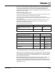
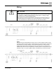
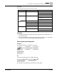
Table 5: Fuse for Heating System.
Designation in wiring diagram = F4 ext.
External power supply
115 Vac
Fuse
2 AT
If actuator controls are mounted separately from actuator (actuator controls on wall
bracket): Consider length and cross section of connecting cable when defining the
protection required.
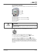
Potential of customer connections
All input signals (control inputs) must be supplied with the same potential.
All output signals (status signals) must be supplied with the same potential.
Safety standards
Safety measures and safety equipment must comply with the respectively valid
national on-site specifications. All externally connected devices shall comply with the
relevant safety standards for the place of installation.
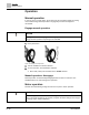
Connecting cables
● We recommend using connecting cables and connecting terminals according to
rated current (I
N
) (see the motor name plate or electrical data sheet).
● For device insulation, use appropriate (voltage-proof) cables. Specify cables for
the highest occurring rated voltage.
● Use connecting cable with appropriate minimum rated temperature.
● For connecting cables exposed to UV radiation (outdoor installation), use UV
resistant cables.
● Use screened cables for the connection of position transmitters.
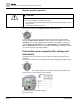
Cable installation in accordance with EMC
● Signal and fieldbus cables are susceptible to interference. Motor cables are
interference sources.
● Lay cables being susceptible to interference or sources of interference at the
highest possible distance from each other.
● The interference immunity of signal and fieldbus cables increases if the cables are
laid close to the ground potential.
● If possible, avoid laying long cables and ensure that they are installed in areas
with low interference.
● Avoid parallel paths with little cable distance of cables being either susceptible to
interference or interference sources.