
Operating Instructions

Assembly
Mounting the actuator
A6V12052002
19 | 80
Mounting the actuator
NOTICE
Danger of corrosion due to damage to paint finish and condensation!
● Touch up any damage to the paint finish after working on the device.
● After mounting, connect the device immediately to electrical mains to ensure that
heater minimizes condensation.
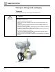
Mounting to valve/gearbox
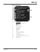
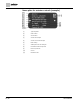
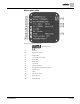
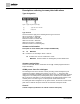
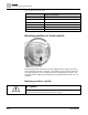
Figure 8: Mounting output drive types B
[1]
Multi-turn actuator
[2]
Valve/gearbox
[3]
Valve/gearbox shaft
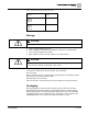
1. Check if mounting flanges fit together.
2. Check if output drive of multi-turn actuator [1] matches the output drive of
valve/gearbox or valve/gearbox valve shaft [2/3].
3. Apply a small quantity of grease to the valve or gearbox shaft [3].
4. Fit multi-turn actuator [1].
Information: Ensure that the spigot fits uniformly in the recess and that the
mounting faces are in complete contact.
5. Fasten multi-turn actuator with screws according to table.
Information: We recommend applying liquid thread sealing material to the screws
to avoid contact corrosion.
6. Fasten screws crosswise to torque according to the following Table Tightening
Torques for Screws.
7. Turn multi-turn actuator with handwheel in the OPEN direction until the valve
flange and output drive Type A firmly connect.
8. Tighten fastening screws (5) between the valve and output drive Type A
crosswise, applying torque according to the above table.