
Installation Guide

Optional Outlet
Installation
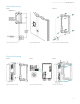
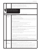
STEP Standard Mounting
(Recommended)
. Locate a stud within the wall that can handle the + lb. load of the VersiCharge.
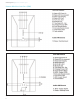
. Place the mounting bracket not more than ” above a V outlet; level the mounting and drill the center-top hole using
aathe drill with an extender.
. Secure the mounting with the kit-supplied screws.
. Drill the bottom hole using the bottom-center mounting hole as a guide.
. Secure with the kit-supplied screw.
. Tighten both top and bottom screws securely.
For concrete cinder block walls, install appropriate anchors. If using an existing outlet, ensure that power cord will reach to
the outlet. Using a /” socket, attach mounting bracket to wall in compliance with all National Electrical Code® (NEC) and
local jurisdiction requirements, using the lag screws provided.
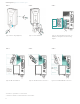
STEP A Alternate Mounting NOTE: Anchor Rating: anchors must be rated as lb. anchors rated for /” dry wall .
The VersiCharge can be mounted using - # x -½ LG Phillips head . head minimum with - # wall anchors.
. Locate the mounting bracket not more than ” above a V outlet or if hardwiring, the wiring will come through the
bottom of the charger.
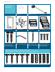
. Level the mounting bracket and drill holes, one in each corner of the bracket.
. Place anchors into the wallboard until they are flush with the wall.
. Place the mounting bracket over the holes (hinges facing upward, flat side of the bracket against the wall) with the
anchors and screw the mounting to the wall securely.
. Add a th hole for mounting the holster once the unit is mounted on the wall. Place the holster on the wall and mark
the correct position for the hole. Refer to Step and its graphic.
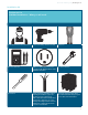
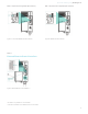
STEP Install/Mount Charger NOTE: For installation, the mounting-bracket hinges will be pointing to the ceiling, and the flat side of the bracket will be
against the wall.
. Slide the VersiCharge on to the hinges.
. Rotate to the right until the unit clicks and is closed.
. Secure the enclosure with the locking mechanism and plug the VersiCharge into the V outlet. If hardwiring the unit,
aasee Hardwire Installation in Step .
STEP Set Amp Switch
DANGER Hazardous voltage. Will cause death or
serious injury. Turn off power before working on this
equipment. This indicates a situation where the present
voltage could cause injury or death. Extreme caution is
required when servicing or installing the equipment
referenced.
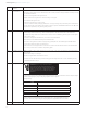
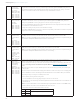
The VersiCharge comes set to the maximum of the model purchased (i.e. a amp model will not exceed amps but may be
derated for lower amperage by using the amperage adjustment dial). See Figure .
Amperage Settings
Switch Positionwitch
Position
Amps
0 12
1 16
2 24
3 32
4 40
5 48
NOTE: Settings: 0 - 4 amperage adjustment settings are used for the 40 amp charger (note: the #5
position will cause a bad switch fault for the 40 amp charger) and 0 - 5 amperage adjustment settings
are used for the 48 amp charger. Setting the amperage adjustment higher than 5 will result in a fault.
STEP Close the Charger
VersiCharge™ AC | Quick start installation guide