
Installation Guide

STEP Connect Ethernet
(Residential and
Commercial Units)
Part numbers:
EM-CF-FA,
EM-CF-FA,
EM-CF-GA,
EM-CF-GA,
EM-CF-GA,
EM-CF-GA
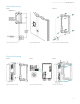
NOTE: The Ethernet cable connector should NOT be on the Ethernet cable when it is pushed through the rubberized gland.
This gland will not self-seal if the connector is pushed through the rubberized gland and the NEMA rating will be lost.
Push the Ethernet cable through the rubberized gland and snake it up through the back to the opening. Connect the
Ethernet connector and insert the connector from the bottom up into the Ethernet connection.
STEP Connect ModBus
RS (Commercial
Units Only)
Part numbers:
EM-CF-GA,
EM-CF-GA,
EM-CF-GA,
EM-CF-GA
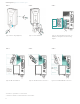
NOTE: The ModBus connector should NOT be on the Modbus cable when it is pushed through the rubberized gland. This
gland will not self-seal if the connector is pushed through the rubberized gland and the NEMA rating will be lost.
. Using the supplied ModBus connector gently press the connector into place (see Figure ).
. Push the external ModBus cable through the rubberized gland at the back of the charger (this will self-seal). Attach
the external wires to the internal wire connector.
. Gently tuck the wiring into the space and secure the back of the charger.
Security Note: The ModBus RTU is an open protocol, and it is the responsibility of the installer to ensure the security of the
wiring of these connections to prevent tampering.
STEP A Set ModBus
Termination Switch
(Commercial Units
Only)
Part numbers:
EM-CF-GA,
EM-CF-GA,
EM-CF-GA,
EM-CF-GA
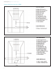
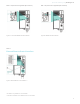
SW- (left side) labelled A RS is the Termination switch. This switch should be in the ON position for the Parent unit or
in the OFF position for a Child unit, unless that Child is the last Child in the daisy chain, then it must be ON.
NOTE: For more detail on the ModBus and the Termination Switch position settings, refer to the complete VersiCharge AC
Series Installation and Operation Manual at www.usa.siemens.com/versicharge.
STEP B Set ModBus
Termination Switch
(Commercial Units
Only)
Applicable to Child
units ONLY with the
following part
numbers:
EM-CF-GA,
EM-CF-GA
SW- (right side) labelled M RS Term is the Termination switch. For the child units the Termination switch must be set
to OFF, unless the unit is the last one in the daisy chain, then the switch must be set to ON.
NOTE: For more detail on the ModBus and the Termination Switch position settings, refer to the complete VersiCharge AC
Series Installation and Operation Manual at www.usa.siemens.com/versicharge.
STEP Connect External
Remote Control
Interface – (Optional)
(Commercial and
Residential Units)
Part numbers:
EM-CF-FA,
EM-CF-FA,
EM-CF-GA,
EM-CF-GA,
EM-CF-GA,
EM-CF-GA
The Siemens VersiCharge has a Remote Control Interface that allows charging to be controlled by an external device.
Examples include demand response switches, building automation systems, digital sensors, etc.
• To wire a digital input into the dry contact in the connection area located inside of the VersiCharge, please refer to the
complete VersiCharge AC Series Installation and Operation Manual at www.usa.siemens.com/versicharge for more
detail.
• When the external contact is closed, the alternate input will control the VersiCharge, preventing it from entering the
‘Charging’ state.
• The status output is a switch that indicates charging status. When the contacts are closed, the unit is in charging state.
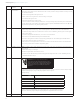
. Remove the Multi-use Connector from the bag and wire an additional remote control interface cable to pins # and #.
. Open hinged cover by loosening four cover Phillips closure screws.
. Remove barrier by removing the two securing screws.
. Connect to the Multi-use connector by gently pressing the connector on to the connector.
. Press the Remote Control cable through the rubberized gland at the back of the unit without the connector attached. This
gland will self-seal.
NOTE: Do not press the cable with the connector attached through this gland, that will cause the loss of the NEMA rating.
. Attach the Remote Control cable connector and attach the two cable connectors.
. Gently tuck the cables into the back of the unit and close the case.
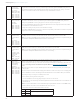
Pin # Label Description
7 Utility_1 Utility lockout (dry contact input; locked when closed)
9 Utility_2
VersiCharge™ AC | Quick start installation guide