Quick start installation guide VersiCharge™ AC Electric vehicle charging station usa.siemens.
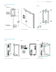
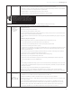
VersiCharge™ AC | Quick start installation guide Human Machine Interface (HMI) Figure 1. Residential HMI NOTE: Number of LEDs may change based on specific part number and features. Figure 2. Commercial HMI NOTE: Number of LEDs may change based on specific part number and features.
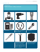
Quick start installation guide | VersiCharge™ AC Installation kit Equipment List Standard Installation – What you will need: Certified Electrician (Recommended) Cordless Drill (Phillips Bit with extender) Stud Finder 240 V AC Voltmeter NEMA 6-50 Outlet (Only used for the 40A charger P/Ns 8EM1312-4AF10-0AA3, 8EM1312-4CF18-0FA3.) 7/16” Socket wrench Screwdriver #6 75C copper wire should be used for 48A charger and #8 75C copper wire should be used for a 40A charger. NOTE: 1.
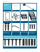
VersiCharge™ AC | Quick start installation guide Kit Supplied Equipment 1 – Ferrite Core 1 – ModBus Connector User Card User Card Admin Card User Card Admin Card User Card User Card 1 – Mounting Bracket 1 – Cable Holster 2 – Admin Cards 5 – User Cards 2 – Lag Screws, Hex Head screws, 1/4 x 2” (for securing the mounting bracket to the wall studs) Tamper resistant 5/32” Allen wrench (secure the charger) 1 – #8 x 2-1/2” Flat Head Drywall Screw (for securing the holster to the wall stud) 3 – #10-
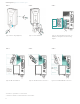
Quick start installation guide | VersiCharge™ AC Bracket Mounting: STEP 1 STEP 1A Figure 3. Bracket Position Figure 4. Wall Mounting Figure 5. Alternate Bracket Mounting Charger Mounting: STEP 2 STEP 3 STEP 4 Figure 6. Hanging Charger Figure 7. Amp Switch Setting Figure 8.
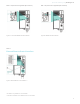
VersiCharge™ AC | Quick start installation guide STEP 5 STEP 6 STEP 7 P1 - Black Hot/Power P2 - Green Ground/Earth P-3 - Red Hot/Power Ferrite Core Figure 9. Secure Charger (Optional) Figure 10. Holster Installation Figure 11. Charger Hardwiring and Ferrite Core Installation. See Appendix C for wire bending diagram. STEP 8 STEP 9 STEP 10 Figure 12. SIM Card Installation* Figure 13. CAT6 Ethernet Port Connection** Figure 14.
Quick start installation guide | VersiCharge™ AC STEP 10A (See below for applicable part numbers) STEP 10B (See below for applicable part numbers) Figure 15. Commercial ModBus Termination Switch* Figure 16. ModBus Termination Switch* STEP 11 External Remote Control Interface Figure 17. External Remote Control Interface** *This feature is only available on Commercial Units. **This feature is available on both Residential and Commercial Units.
VersiCharge™ AC | Quick start installation guide Optional Outlet Installation STEP 1 Standard Mounting (Recommended) 1. Locate a stud within the wall that can handle the 17+ lb. load of the VersiCharge. 2. Place the mounting bracket not more than 12” above a 240 V outlet; level the mounting and drill the center-top hole using aathe drill with an extender. 3. Secure the mounting with the kit-supplied screws. 4. Drill the bottom hole using the bottom-center mounting hole as a guide. 5.
Quick start installation guide | VersiCharge™ AC STEP 5 Secure Charger and Install cable holster 1. Secure Charger to Mounting Bracket: Using the kit-supplied tamper-resistant screw– secure the charger cover with one screw on the side. Use the second screw (underneath the charger) to secure Front Cover to the Charger. 2. Install Holster to Charger: Align Holster with guides in charger.
VersiCharge™ AC | Quick start installation guide STEP 8 Connect Ethernet (Residential and Commercial Units) Part numbers: 8EM1312-4CF18-0FA3, 8EM1312-5CF18-0FA3, 8EM1310-4CF14-0GA0, 8EM1310-5CF14-0GA0, 8EM1310-4CF14-1GA1, 8EM1310-5CF14-1GA1 STEP 9 Connect ModBus RS485 (Commercial Units Only) Part numbers: 8EM1310-4CF14-0GA0, 8EM1310-5CF14-0GA0, 8EM1310-4CF14-1GA1, 8EM1310-5CF14-1GA1 STEP 9A Set ModBus Termination Switch (Commercial Units Only) NOTE: The Ethernet cable connector should NOT be on the E
Quick start installation guide | VersiCharge™ AC STEP 11 Check the System Turn the power on; the white Power Available light should illuminate. If it does not, verify that the outlet or wire is putting out 240 or 208 V using the voltmeter. With the Power Available light on, plug the Electric Vehicle Supply Equipment (EVSE) cable into the car. If you have any fault lights, please see the HMI figures in the beginning of this manual.
VersiCharge™ AC | Quick start installation guide Maintenance While there is no maintenance for the internal works of the VersiCharge, the exterior does require some basic, common sense maintenance. The following maintenance can be performed by the owner/user. All other service must be conducted by qualified personnel. If there is any damage to the charger, contact your supplier. General exterior maintenance is recommended to be performed every six months depending on the environment.
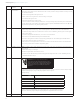
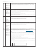
Quick start installation guide | VersiCharge™ AC APPENDIX A – System Operation/Faults Wi-Fi LED Light Sequence When Adding a Charger Description of Sequence LED Color (Blinking) LED Color (Steady) Power up Software loading Software running Charger in Access Point (AP) mode Receiving connection credentials Received connection credentials Connecting to network Connected to network Connecting to VersiCloud Connected to network, registered and connected to VersiCloud NOTE: Grey LED Color indicates no lit LE
VersiCharge™ AC | Quick start installation guide Light State Description Solution #9 – Touch Sensitive Button – Reset Ground Fault – Press once to reset the unit. The unit is in a fault state. Press one time to reset the ground fault. #4 Fault occurring – Power cycle/turn breaker off and then on Faults Light #9 Light #4 Light flashing red Light # 4 #4 + #7 (4 hr. delay light) – Light # 7 Lights steady red Light # 4 #4 + #7 (2 hr.+4 hr.
Quick start installation guide | VersiCharge™ AC APPENDIX B – Useful Links Find the following at: usa.siemens.com/versicharge • Register your VersiCharge • Download the VersiCharge Configuration Tool (PC application) • Configure your VersiCharge • VersiCharge Frequently Asked Questions • Detailed VersiCharge Installation and Operating Manual, as well as all legal and warranty information.
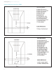
VersiCharge™ AC | Quick start installation guide APPENDIX C – Hardwire Bending Diagram Dedicated 2 Pole 50/60 amp commom trip branch circuit breaker 16
Quick start installation guide | VersiCharge™ AC Notes: 17
VersiCharge™ AC | Quick start installation guide Notes: 18
Quick start installation guide | VersiCharge™ AC Notes: 19
Published by Siemens Industry, Inc. 2020 Siemens Industry, Inc. 3617 Parkway Ln. Peachtree Corners, GA 30092 Phone: +1 (800) 333-7421 helpline.sii@siemens.com usa.siemens.com/versicharge Engineering doc no: R815073 Article No. SIDS-T40066-00-4AUS Printed in USA All Rights Reserved © 2020, Siemens Industry, Inc.