
Product Overview

Document No. 129-427
Installation Instructions
October 5, 2009
Information in this publication is based on current specifications. The company reserves the right to make changes in specifications and
models as design improvements are introduced. Powers is a registered trademark of Siemens Industry, Inc. Product or company names
mentioned herein may be the trademarks of their respective owners. © 2009 Siemens Industry, Inc.
Siemens Industry, Inc.
Building Technologies Division
1000 Deerfield Parkway
Buffalo Grove, IL 60089
+ 1 847-215-1000
Your feedback is important to us. If you have
comments about this document, please send them
to sbt_technical.editor.us.sbt@siemens.com
Document No. 129-427
Printed in the USA
Page 2 of 2
2. Verify that the room temperature is between
70°F and 80°F (21°C and 27°C).
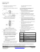
3. Construct pressure gauge assembly as shown in
Figure 2.
Figure 2. Pressure Gauge Assembly.
4. Loosen test screw (see Figure 3) using a
screwdriver, 1/2 turn counterclockwise.
Figure 3. Test Screw Location.
5. Attach the 3/16-inch ID rubber hose on the
pressure gauge assembly over the test screw
body.
6. Stand away from thermostat for about five
minutes to prevent body heat temperature
influence. If control pressure does not read 7 psi
to 8 psi (48 kPa to 55 kPa), turn adjustment
screw with the D Adjustment Key as follows:
• If less than 7 psi to 8 psi (48 kPa to
55 kPa), turn the adjustment screw
clockwise.
• If greater than 7 psi to 8 psi (48 kPa to
55 kPa), turn the adjustment screw
counterclockwise.
If there is no change in pressure, the thermostat
is not functioning and should be replaced with
Part Number 832-040 D Thermostat
replacement unit.
If the dial reading and room temperature do not
agree, loosen dial retaining screw with a
screwdriver. (SeeFigure 3.)
1. Tilt and rotate until dial reading agrees with
room temperature. Do not turn dial pinion.
2. Retighten dial retaining screw.
3. Remove the D Adjustment Key and pressure
gauge assembly, and let pressure stabilize.
4. Verify that the control pressure remains between
7 to 8 psi.
5. Stand away from thermostat for about five
minutes. If control pressure does not read 7 to 8
psi (48 to 55 kPa), turn adjustment screw with
key (Part Number 856-055) until this pressure is
obtained.
6. If the dial reading and room temperature do not
agree, loosen dial retaining screw.
(See Figure 3.)
7. Tilt and rotate until dial reading agrees with
room temperature. Do not turn dial pinion.
Retighten dial retaining screw.
8. Replace the thermostat cover and tighten the
two vandal-proof, chrome screws.
The instrument is now in calibration and can be set
to the desired room temperature.
Service Kits
Product
Number
Description
832-040
D thermostat chassis without cover
and base
832-164
Exhaust Supply Valve Repair Kit
832-034
Base Kit for mounting D thermostat
with exposed tubing
856-036
Replacement cover for 832-0120
856-046*
Replacement cover for 832-0490
856-044
Replacement cover for 832-1260 or
832-0500
* Two 856-014 screws are required with this cover.