
Install Instructions
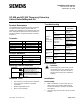
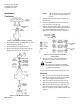
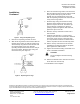
Table Of Contents

Document No. 129-187
Installation Instructions
September 25, 2009
Page 2 of 3 Siemens Industry, Inc.
Installation,
Continued
Figure 1. Removing the Actuator Assembly.
3. Unscrew the actuator assembly from the valve
stem. Remove the actuator.
4. Remove and retain the stem locknuts.
5. Remove and discard the lower seat from the
bottom of the valve body. See Figure 2.
Figure 2. Valve Body Construction.
NOTE: The old lower seat must not be used
with the stem assembly provided in
this kit.
6. Pull the stem and throttle plug assembly out of
this opening.
7. Using an adjustable wrench, remove the cap
from the bonnet. Keep the cap.
8. Remove and discard all packing. See Figure 3
which shows the various packing configurations
you will find depending on the model of the
valve. Do not reuse any of these components.
Figure 3. Previous and Current Packing
Configurations.
9. The bottom packing ring can be difficult to
remove. Use a pick to carefully remove it.
CAUTION:
Be careful not to damage the packing
chamber when removing the old packing
or cleaning the chamber.
10. Clean the packing chamber. Remove any dirt.
Assembly
1. Slide the new stem and throttle plug assembly
into bonnet through the opening in the bottom
of the valve body as shown in Figure 2.
2. Place the new O-ring and new lower seat on
the bottom of valve body and tighten securely.
3. Slide the new packing ring over the stem and
push it to the bottom of the packing chamber
with the repacking tool (included in the kit). See
Figure 4.