
Install Instructions
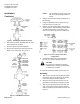
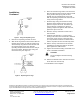
Table Of Contents

Document No. 129-187
Installation Instructions
September 25, 2009
Information in this publication is based on current specifications. The company reserves the right to make changes in specifications and
models as design improvements are introduced. Teflon is a registered trademark of DuPont. Product or company names mentioned herein
may be the trademarks of their respective owners.©2009 Siemens Industry, Inc.
Siemens Industry, Inc.
Building Technologies Division
1000 Deerfield Parkway
Buffalo Grove, IL 60089-4513
U.S.A.
Tel. +1 847-215-1000
Your feedback is important to us. If you have
comments about this document, please send them
to sbt_technical.editor.us.sbt@siemens.com
Document No. 129-187
Printed in the U.S.A.
Page 3 of 3
Installation,
Continued
Figure 4. Using the Repacking Tool.
4. Remove the repacking tool from the stem.
5. Slide the O-ring retainer into the bonnet with the
tapered surface facing up. Slip the small O-ring
and the backup ring over the stem threads onto
the smooth portion of the stem. With the
repacking tool push both down into the cavity of
the O-ring retainer. Slide the large O-ring into
the bonnet cavity. See Figure 5.
Figure 5. Repacking the O-rings.
6. Place the second O-ring retainer into the bonnet
with the tapered surface facing up. Slip the small
O-ring and the backup ring over the stem
threads onto the smooth portion of the stem.
With the repacking tool push both down into the
cavity of the O-ring retainer.
7. Slide the large O-ring into the bonnet cavity.
Slide the copper washer onto the stem and
place the cap over the stem. Thread the cap
onto the bonnet. Hand tighten to bring all
packing components together. With a wrench,
tighten the cap to 10 ft.-Ibs.
8. Move the stem up and down to make sure it
does not bind.
9. Install the stem locknuts. To ensure proper
seating of the valve when the bonnet is attached
to the body, there must be at least 1/16-inch
(1.6 mm) clearance between the lower locknut
and the cap when the stem is all the way down.
10. Pull the stem up and attach it to the actuator
assembly by screwing the stem into the piston
plate. Tighten the stem locknuts.
11. Tighten the two lower housing screws with a nut
driver or flat blade screwdriver.
CAUTION:
Do not overtighten the lower housing
screws.
12. Restore the medium to the valve and reconnect
the air line to the actuator top.
The installation is now complete.