
User Guide


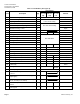
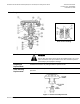


Table Of Contents

Technical Instructions
Document No. 155-092P25
November 20, 2008
Page 4 Siemens Industry, Inc.
Operation
The sequence valve, (Figure 3), is piped to the inlet of a coil. Therefore, it has hot water
supply and chilled water supply connected to it. The changeover valve, (Figure 4), is piped
to the outlet of the coil. Therefore, it has the hot water and chilled water returns connected to
it. For the sequence valve, water should flow into the hot and cold ports and out of the
common. For the changeover valve, flow should be into the common and out of the hot and
cold ports.
The operation of the sequence valve and changeover valve is similar. The main difference is
the control pressure at which the upper port opens and the lower port closes on each valve.
With no air pressure to the Powertop the chilled water port (upper disc) is closed and the hot
water port (lower disc) is open. As air pressure increases, the lower disc is gradually moved
toward its seat, reducing the flow of hot water. After the lower disc closes against its seat,
stopping the flow of hot water, there is a dwell period (dependent upon water differential
pressures) during which there is no flow through the valve. As the control air pressure
continues to increase, it overcomes the disc spring force to gradually move the upper disc
away from the seat permitting the flow of cold water.
As the differential water pressure increases, the hot port (lower disc) will close at a higher
Powertop pressure and cold port (upper disc) opens at a lower Powertop pressure. The
effect is to narrow the dwell period.
Figure 1 shows the nominal control schedule for the sequence and changeover valves.
Figure 3. Sequence Valve.
Figure 4. Changeover Valve.