
User Guide


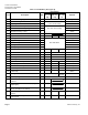
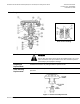


Table Of Contents

Technical Instructions
Document No. 155-092P25
November 20, 2008
Page 2 Siemens Industry, Inc.
Specifications
Valve Body
Valve size/ capacity See Tables 1 and 2.
Body Style 1/2” SAE Flared
Body type Sequence 2 inlets, 1 outlet
Changeover 1 inlet, 2 outlets
Action Normally Open (NO) Hot to common
Normally Closed (NC) Cold to
common
Valve stroke 13/32-inch (10 mm)
Material
Body Bronze
Seat Bronze
Stem Stainless steel
Stem packing (O-rings) EP rubber
Shut-off disc Buna-N
Throttle plug Brass
Valve Actuator
Nominal spring range See Figure 1.
Diaphragm
Effective area 11 inch
2
(71 cm
2
)
Material EP rubber
Max. air pressure 30 psig (210 kPa)
Operating
Controlled medium Water, ethylene glycol solution
Flow characterization:
Sequence Equal percentage
Changeover Quick opening
Ambient temperature range 35°F to 140°F (2°C to 60°C)
Body rating, max temperature/pressure See Table 3.
Max. pressure difference between hot
and cold ports:
Sequence 50 psig (350 kPa)
Changeover 10 psig (69 kPa)
Max. differential pressure
for modulating service (sequence) 25 psi (170 kPa)
Dimensions See Figure 8.
Application
A typical application of sequence and changeover valves controls heating or cooling in a
single coil or radiant panel. These four-pipe systems have hot water and chilled water
available at the same time. Figure 2 shows a unit conditioner application.
The direct acting thermostat gradually positions the sequence valve and the changeover
valve to maintain space temperature according to the control schedule shown in
Figure 1. The sequence valve gradually controls the hot or chilled water flow into the
coil. The changeover valve diverts the water leaving the coil to the correct return line.