
Data Sheet for Product


Powertop Two-Way Valves Normally Open Technical Instructions
Document No. 155-310P25
July 18, 2012
Siemens Industry, Inc. Page 5
Installation
NOTE: Install the valve in any position except upside down. The preferred installation
position is upright.
In concealed installations, allow three inches (75 mm) from the top of the actuator to
remove the upper housing for valve servicing.
CAUTION:
Never use the valve housing as a lever arm to
tighten the body when taking up on a thread.
Install the valve so that the flow follows the direction arrow cast on the valve body.
Install hand valves on supply and return piping to allow for servicing.
Service
Diaphragm replacement
Instructions for replacement are included in the kit.
Stem packing
Instructions for repacking the valve stem are included in the kit.
Valve disc replacement
Instructions for replacing the valve disc are included in the kit.
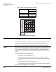
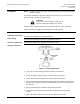
Actuator replacement
Figure 2. Actuator Replacement.
1. Loosen the two lower housing screws that clamp it to the bonnet.
2. Loosen the stem lock nuts using two 7/16-inch open-end wrenches.
3. Unscrew the actuator assembly from the stem as shown in
Figure 2.
4. Push the stem all the way down before installing the new actuator assembly. There
must be at least 1/16-inch (2 mm) clearance between the lower stem lock nut and
the valve cap.
5. Pull the stem back up and install the new actuator assembly.
6. Screw the stem into the actuator piston plate and tighten the lock nuts with a
wrench.
7. Tighten the lower housing screws. Do not over-tighten these screws.