
User manual
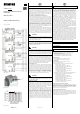
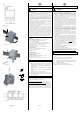
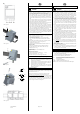

Bild / Figure 4
Bild / Figure 5
Bild / Figure 6
Bild / Figure 7
Bild / Figure 8
GB
Technical Specifications, continued
V
DANGER
• If the device is mounted in a cavity floor or is used for over-
head or horizontal installation the reduction of the maxi-
mum connected power as shown in figure 3 applies.
• Connecting mixed loads to the same output (both inductive
and capacitive loads, e.g. a group of low voltage halogen
lamps with magnetic transformer, together with a group of
low voltage halogen lamps with electronic transformer or
together with dimmable energy-saving lamps) is not permit-
ted.
• Low voltage halogen lamps with an electronic transformer
may only be used in mixed operation together with incan-
descent lamps and high voltage halogen lamps.
• Magnetic transformers may only be used if they comply with
the relevant standards and contain a thermal fuse.
• Low voltage halogen lamps with a magnetic transformer
may only be used at the same output together with incan-
descent lamps and dimmable energy-saving lamps from Os-
ram if the parameter "Load adaptation" has been set from
"Automatic load adaptation" to "Leading edge control".
• With Osram's dimmable energy-saving lamps, the parameter
"Load adaptation" must be set from "Automatic load adapta-
tion" to "Leading edge control” and the parameter "Minimum
dimming value" to a value > 20%.
Connections
• Mains, load and pushbuttons connections: Screw-type termi-
nals, insulation strip length 7... 9 mm
The following conductor cross-sections are permitted:
- 0,5... 4.0 mm² single core,
- 0,5... 2.5 mm² finely stranded, without / with connector
sleeve
• Submodule: Low voltage terminal block, screwless, conduc-
tor cross-section 0.6 … 0.8 mm Ø single core,
insulation strip length 5 mm,
maximum length of cable between modules A and F: 2 m
Mechanical data
• Dimensions: Installation device for DIN-rail mounting,
N-system dimensions, width: 3 MU (1 MU = 18 mm)
• Weight: approx. 125 g
Electrical safety
• Degree of protection (to EN 60529): IP 20
Environmental conditions
• Ambient temperature in operation: - 5 ... + 45 °C
• Storage temperature: - 25 ... + 70 °C
• Relative humidity (non-condensing): 5% to 93%
Location / Function of the Display and Operating Elements
See figure 4
B1 Plug for low voltage terminal block for connecting uni-
versal dimmer submodules
B2 Screw terminals for connecting/looping the N-conductor
B3 Screw terminals for connecting/looping the L-conductor
B4 Screw terminals for connecting the load
B5 Screw terminals for connecting in each case a pushbut-
ton for direct switching and dimming of the load con-
nected to the output
Mounting and Wiring
The device may be used for permanent interior installations in
dry locations within distribution boards or small casings with
DIN rail EN 60715-TH35-7.5
Mounting and dismounting the device: see figures 5 and 6
Connecting a universal dimmer submodule: see figure 8
Snap the universal dimmer submodule on to the top hat rail and
interconnect the T+ and T- connections from the universal dim-
mer main module and the universal dimmer submodule via a
twisted pair of wires. Connecting the twisted pair of wires to
the low voltage terminal block: see figure 7.
Page 2 of 2
GB
Mounting and wiring, continued
V
DANGER
• The device may only be installed and commissioned by an
authorized electrician.
• If the phase conductor connected to the device is to be
looped to one or more submodules, then the phase conduc-
tor is to be fused with a miniature circuit breaker with B or C
characteristic for a rated current of 16A, in order that the
maximum permissible terminal current is not exceeded.
• If the main module and the submodules connected to it are
to be used on more than one phase, then the third harmon-
ics of the load currents are summed in the jointly fed neutral
conductor. In this way, the neutral conductor can be loaded
more heavily than the phase conductors. The neutral con-
ductor in this case is to be rated adequately or protected
against excessive current, as there may otherwise be a fire
risk.
• Running magnetic transformers at no load is prohibited both
on start-up and in operation, because this may lead to dam-
age to the device (even when the dimmer has cut off). This
is to be ensured by connecting at least two lamps or trans-
formers in parallel to an output. Failed lamps are to be re-
placed immediately.
• The device may only be operated vertically with the ventila-
tion slots at the top and at the bottom. The device must be
well ventilated. Heat dissipation must be ensured.
• This device contains a varistor. Due to a disruption of the
neutral conductor, overvoltage or conventional transformers
running at no load, damage may arise which can lead to the
failure of the device at a later date. The conductors (outer
and neutral conductor) are to be connected with each other
for dielectric tests.
• For dielectric tests of cables, which measure core against
core contrary to the current valid norm DIN VDE 0100 T. 610,
the device must be disconnected, because otherwise it may
be damaged.
• When connecting the device, it should be ensured that the
device can be isolated.
• The device must not be opened.
• For planning and construction of electrical installations, the
relevant guidelines, regulations and standards of the respec-
tive country are to be considered.
General Notes
• The operating instructions must be handed over to the client.
• Any faulty device is to be sent together with a return delivery
note of the local Siemens office to:
Siemens AG, Siemensstr. 10, D-93055 Regensburg
• For any technical questions, please consult:
Tel.: +49 (0) 180 50 50-222 (0.14 €/minute from the
German fixed line network, different mobile wireless
prices possible)
Fax: +49 (0) 180 50 50-223
E-Mail: support.automation@siemens.com
Website: www.siemens.com/automation/service&support
D2
D2.4
D2
D2.4
5 mm
D2.1 D2.2
2
D2.3
D
A5E01278691E
DS 05
B1
B2
C1
C2
D2
D
1