
User manual

GAMMA instabus
N 527/51 Universal dimmer 1000 VA,
submodule
5WG1 527-1AB51
Operating and Mounting Instructions
As at: June 2009
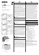
Bild / Figure 1
Bild / Figure 2
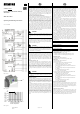
%
100
80
60
40
20
0
020406080 °C
Max. Anschlußleistung
Max. connected load
Umgebungstemperatur
Ambient temperature
Bild / Figure 3
GB
Product and Applications Description
The universal dimmer submodule N 527/51 is an installation
device for DIN-rail mounting, in N-system dimensions. It is de-
signed for lighting control, i.e. for switching and dimming resis-
tive, inductive or capacitive loads from 20 to 1,000 VA at 230V
AC, 50-60 Hz. It is connected to a universal dimmer main mod-
ule or to a preceding submodule via a low voltage terminal
block. The power supply for the electronics is provided by an in-
tegrated 230V AC power supply unit.
Connecting universal dimmer submodules
You can connect a universal dimmer submodule N 527/51 (see,
for example, device E in figure 1) with the 2-pin interface T+, T-
(see figure 1, device A) of a universal dimmer main module
N 528/31 (dimmable load 20-300 VA) or a main module
N 527/31 (dimmable load 20-500 VA) via a twisted pair of
wires. Up to 5 universal dimmer submodules can be connected
to a universal dimmer main module, in which the twisted pair
T+, T- is also to be looped from interface to interface. In this
way, a main module can be extended if required from a KNX
dimmer with one output to a KNX dimmer with up to 6 outputs.
When connecting a new universal dimmer submodule to a main
module please keep in mind to connect first their 2-pin inter-
faces before applying the mains voltage to the submodule(s).
Through this a safe data transmission from the main module to
the submodule(s) will be safeguarded.
V
DANGER
• The lines T+ and T- are to be installed safely isolated from the
230V potential. The maximum permitted line length be-
tween the main module and the submodule furthest away is
2 m.
Dimming loads from 40 to 2000 VA
The outputs from two N 527/51 universal dimmer submodules
(dimmable load each 20-1000 VA) can be connected in parallel,
in order to be able to dim a load in the range from 40-2000 VA
(see devices E and F in figure 1).
V
DANGER
• You must not connect the outputs from more than two
N 527/51 devices in parallel. Parallel operation of the out-
puts from universal dimmer main modules with each other
or with a submodule, as well as of all other universal dimmer
sub-modules, is not permitted!
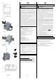
Device address
You set to which dimming channel (B...F) of the main module
the relevant submodule is to be assigned with a rotary switch
on the underside of the housing (see A1 in figure 2). A universal
dimmer main module must always be set on channel A. If two
or more devices are set incorrectly to the same address, then
the light emitting diodes (LED) for the relevant channels flash
green.
Pushbutton inputs E1, E2
A conventional pushbutton can be connected each to the E1
and E2 inputs of the submodule for direct switching and dim-
ming of the output. Tapping the pushbutton on the E1 input
leads to switching on, holding it down to dimming brighter,
tapping the pushbutton on the E2 input leads to switching off,
holding it down to dimming darker. You use a parameter to set
whether pressing one of the buttons is also to lead to sending
switching and dimming telegrams via the bus to other actua-
tors.
V
DANGER
• On electrical safety reasons, both pushbuttons must be con-
nected to the same phase conductor as the dimmer module
in question.
Application program
A universal dimmer submodule has its own application program
as firmware, supporting the autonomous operation of the sub-
module even if it is not connected with a main module (or if the
communication with the main module fails) by switching and
dimming the load via pushbuttons connected to the inputs E1
and E2.
The extensive application program of a main module, which is
configured and loaded with the Engineering Tool Software
(ETS) from ETS 3.0 release f onwards, controls both the output
from the main module and the outputs from all connected
submodules. Inter alia, it includes monitoring of each output for
short circuit, overload and temperature rise, status objects for
reporting switching and dimming status, a warning prior to
switching off, time functions, blocking and releasing an output,
a configurable behavior at bus voltage failure and recovery, as
well as on mains voltage recovery and an integrated 8-bit scene
control in which each output can be integrated in up to 8
scenes.
Page 1 of 2
GB
Product and Applications Description, continued
Behaviour at voltage failure / recovery
Because the power for the submodule's electronics is generated
via an integrated 230 V AC power supply unit, a mains voltage
failure means that the affected output is switched off and that
this module fails completely. The submodule will remain
switched off after mains voltage recovery if the main module
didn´t receive any switching or dimming commands for this
module during mains voltage failure at it. Otherwise the main
module will transmit the last meanwhile received switching /
dimming command to the submodule after mains voltage re-
covery at this module.
In the event of a mains voltage failure at the main module,
night mode is ended if it is active and the current switching
states and dimming values of all modules (channels) are stored
permanently, in order that they can be regenerated automati-
cally after mains voltage recovery. You use a parameter to con-
figure the behaviour after mains voltage recovery: switching on
all channels, switching off all channels, restoring the switching /
dimming states of all channels at mains voltage failure. How-
ever, if night mode was active before mains voltage failure, this
will not be re-enabled.
In contrast, a bus voltage failure results only in a communica-
tion failure via the KNX bus. But communication between the
main module and all connected sub-modules via the interface
T+ / T- is unaffected by this. Each module retains its current
status. If pushbuttons for direct switching and dimming are
connected to a module's pushbutton inputs E1, E2, you can use
these connected buttons to switch and dim this module. You
can also select each module (i.e. each channel) with the
pushbuttons on the top of the universal dimmer main module
and switch and dim in direct mode. Parameters are used to set
the behaviour in each case on bus voltage failure and on bus
voltage recovery.
Additional Information
http://www.siemens.com/gamma
Example of Operation
See figure 1
Technical Specifications
Power supply
• Rated voltage: 230V AC +10%/-15%, 50-60 Hz
• Rated current: 4.4A
• Power loss if output A = OFF: 0.4 W,
maximum power loss at trailing edge dimming: 5.8 W,
maximum power loss at leading edge dimming: 6.0 W.
Pushbutton inputs
• Rated voltage: 230V AC, 50-60 Hz
• Maximum length of the connecting cable: 100 m
Load output
• Rated voltage: 230V AC, 50-60 Hz
• Rated current: 4.4A
• Connection output at 45°C ambient temperature:
- Incandescent lamps: 20...1,000 W
- High voltage halogen lamps: 20...1,000 W
- Low voltage halogen lamps with electronic transformers:
40...1,000 VA
- Low voltage halogen lamps with magnetic transformers:
20…800 VA
- Osram dimmable energy-saving lamps:
1...10 units 15 VA resp. 20 VA
• Total connection output at 45°C ambient temperature and
parallel operation of 2 modules N 527/51:
- Incandescent lamps: 40...2,000 W
- High voltage halogen lamps: 40...2,000 W
- Low voltage halogen lamps with electronic transformers:
80...2,000 VA
- Low voltage halogen lamps with magnetic transformers:
40…1,600 VA
- Osram dimmable energy-saving lamps:
2...20 units 15 VA resp. 20 VA
Short circuit / overload protection
Electronic protection, i.e. the universal dimmer cuts off if there
is a short circuit or overload. After resolving the short circuit /
overload, the universal dimmer can be reconnected by switch-
ing off and on again or by interrupting the mains voltage until a
period of at least 2 minutes has elapsed.
Temperature rise protection
Electronic protection, i.e. the universal dimmer dims to the
minimum dimming value if the maximum permitted tempera-
ture is exceeded. When the excess temperature has fallen to be-
low the maximum permitted value, the universal dimmer re-
verts to the previous dimming value after 2 minutes.
A5E01278691E
DS 05
A1