
Install Instructions

Document No. 129-216
Installation Instructions
September 29, 2009
Siemens Industry, Inc. Page 5 of 6
Installation, Continued
CAUTION:
Be careful not to nick the seat.
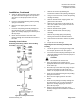
3. Fasten the lower seat into the valve body using
the socket wrench and lower seat tool applying
90 to 100 lb-ft (122 to 130 Nm) torque.
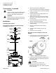
4. Insert the new packing bearing and the packing
spring into the bonnet.
5. Place the new copper gasket on the valve
bonnet.
6. Insert the new packing assembly cartridge into
the valve bonnet. Use a 1-1/2 inch wrench to
tighten the cartridge applying 60 to 65 lb-ft
(80 to 85 Nm) torque.
7. Select the gasket that is marked for the
appropriate ANSI Class valve. Place the gasket
on the service flange.
8. Attach the service flange, if used, to the valve
body using an open end wrench to tighten the
cap screws. See Table 1 for the proper wrench
size and torque.
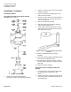
9. Return to the instructions that came in the
packing cartridge kit to assemble the actuator to
the valve.
The installation is now complete.
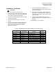
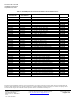
Table 3. Rebuild/Repack Service Kit Part Numbers for Three-way Valves.
ANSI Class 125
Valve Number
ANSI Class 250
Valve Number
Valve
Inch (mm)
Kit
Number
599-06160 599-06170 2-1/2 (65) Bronze trim
599-10125
599-06161 599-06171 3 (85) Bronze trim
599-10126
599-06162 599-06172 4 (100) Bronze trim
599-10127
599-06163 599-06173 5 (125) Bronze trim
599-10128
599-06164 599-06174 6 (150) Bronze trim
599-10129
599-06165 599-06175 2-1/2 (65) Stainless Steel trim
599-10120
599-06166 599-06176 3 (85) Stainless Steel trim
599-10121
599-06167 599-06177 4 (100) Stainless Steel trim
599-10122
599-06168 599-06178 5 (125) Stainless Steel trim
599-10123
599-06169 599-06179 6 (150) Stainless Steel trim
599-10124