
Installation Instructions


Document No. 129-496
Installation Instruction
September 26, 2016
Siemens Industry, Inc. Page 5 of 6
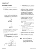
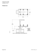
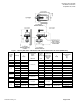
Figure 7. Two-way Ball Valve and Bracket with Actuator Dimensions in Inches (Millimeters).
Line Size
Inches
(mm)
Cv Range
A
Length
C Length *
Actuator Codes
171A-D,
173A-D
GDE/GLB
C Length *
Actuator
Codes
171H,J,K,L,N
GQD
C Length *
Actuator Codes
171E,F,G,M,P
172E,F,G,M,P
Fail-Safe
GMA
F
Height
Valve and Bracket
Weight
lbs
(kg)
1/2 (15)
0.4 to 10
2-7/16 (61)
6-11/16 (170)
6 (153)
─
7-5/8 (193)
1.1 (0.50)
3/4 (20)
6.3 to 25
2-3/4 (70)
6 (153)
─
8 (204)
1.4 (0.60)
1 (25)
10
3 (77)
–
8 (203)
8 (204)
1.6 (0.73)
16, 40, 63
3-1/4 (82)
─
8-3/8 (213)
8-5/15 (212)
1.8 (0.82)
25
3-7/8 (98)
7 (178)
─
8-11/16 (221)
8-13/16 (223)
1.8 (0.82)
1-1/4 30)
16
3-3/8 (86)
6-11/16 (170)
─
8-7/16 (214)
8-3/8 (213)
2.0 (0.91)
25 to 100
3-11/16 (94)
6-15/16 (176)
─
8-11/16 (221)
8-13/16 (223)
2.5 (1.1)
1-1/2 (40)
25, 63
3-5/8 (92)
─
8-7/16 (214)
8-13/16 (223)
1.8 (0.82)
40, 100, 160
3-15/16 (100)
7-1/16 (180)
─
8-3/4 (223)
9-1/4 (235)
3.3 (1.50)
2 (50)
40, 100
4 (102)
─
9-3/8 (238)
3.1 (1.41)
63
4-5/8 (118)
7-1/2 (190)
─
9-1/8 (223)
10-1/16 (255)
5.25 (2.38)
160
–
5.3 (2.40)