
Install Instructions


Document No. 129-496
Installation Instructions
July 21 2010
Installation, Continued
Assembling the Bracket Assembly to
the Valve
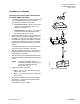
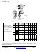
1. Insert the ball valve bracket shaft through the
bottom of the bracket. See
Figure 3.
2. Make sure the ball valve bracket shaft is seated
completely against the bottom of the bracket
3. Rotate the ball valve bracket shaft to the fully
counterclockwise position
4. While holding the shaft in the appropriate
orientation, assemble the bracket to the valve
using the two M4 × 0.7 × 50 mm, or M4 × 0.7 ×
53 mm screws, depending on your
configuration. (See Figure 3.)
EA1232R1
Figure 3.
Normally Open (NO) Valve and Actuator
Assembly:
1. For NO valve applications, you must rotate the
ball valve bracket shaft to the full (90°)
counterclockwise position prior to assembly to
the valve.
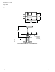
a. Non-installed Valves – Verify that the ball
valve is open by looking into the "A" (inlet)
port to see if it is open. (See
Figure 4.)
EA1288R1
Inlet
Figure 4.
b. Installed Valves –See Figure 1 or Figure
2
to check the stem position with respect to
the flow arrow.
2. The OpenAir GMA actuator comes shipped
from the factory with a 5° preload. This must be
released prior to assembly. The gear train of
the GMA actuator is released by using the
override drive to slightly advance the actuator.
After the gear train lockpin disengages, the
actuator will return to its fail-safe position.
The GQD actuator does not ship with any
preload, and comes ready to assemble to the
valve.
3. Before assembling the GMA or GQD actuator to
the ball valve bracket shaft, make sure the
actuator zero indication on the top of the
actuator is to the left.
4. Slide the actuator over the ball valve bracket
shaft and onto the lowest available step of the
ball valve bracket.
NOTE: The GDE/GLB and GQD will rest on
the lowest step. The GMA will rest
on the second lowest step.
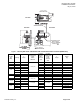
5. Tighten the actuator to the shaft:
a. GDE/GLB – use a 4 mm Allen wrench to
apply 44 to 60 lb-in torque.
b. GMA –- use a 10 mm socket wrench to
apply 60 to 90 lb-in torque
c. GQD – use a 3 mm Allen wrench to apply
44 to 60 lb-in torque.
6. For GDE/GLB actuators, an anti-rotation screw
must be driven in fully. (See
Figure 6 and
Figure 7.)
7. Assemble the handle to the end of the shaft
with the 6/32-inch × 3/4-inch screw provided
until the handle has no free play.
The installation is now complete.
NOTE: Ball valve assemblies with GMA
actuators are shipped from the factory
with shaft adaptors having two sets of
3 mm screws (four total) for shaft
attachment. GMA actuators ordered
separately ship with a self-centering
shaft adapter.
Page 2 of 6
Siemens Industry, Inc.