
Data Sheet for Product


Technical Instructions Flowrite 599 Series SKB/C/D 62UA Electronic Valve Actuator Advanced Features
Document Number 155-717
September 25, 2018
Page 8 Siemens Industry, Inc.
Stroke Calibration
To determine the stroke positions 0% and 100% in the valve, calibration is required when the
valve/actuator are commissioned for the first time. The actuator must be mechanically
connected to a valve and must have a supply voltage of 24 Vac. The calibration procedure can
be repeated as often as necessary
CAUTION:
Before starting calibration, be sure that the manual adjuster is set to Automatic for
the actual values to register.
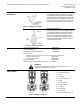
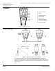
There is a slot on the printed circuit boards for the actuators. To
initiate the calibration procedure, the contacts inside this slot must
be short-circuited (possibly with a screwdriver). See Figure 11.
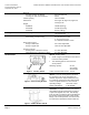
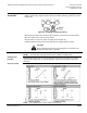
Automatic calibration proceeds as follows (see Figure 12):
• Actuator runs to the 0% stroke position (1), the green LED
flashes.
• Actuator then runs to the 100% stroke position (2), the
green LED flashes.
• Measured values are stored in the EPROM.
• The actuator now moves to the position defined by control
signal Y or Z (3), and the green LED now glows steady
(normal operation).
• Throughout this procedure, output U is inactive, meaning
the values only represent actual positions when the green
LED stops flashing and remains on continuously.
Figure 11.
Figure 12.
Automatic Calibration.
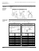
Table 2. LED Status.
LED
Display
Function
Action
Green
ON
Normal Operation
Automatic operation
Flashing
Stroke calibration In
Progress
Wait for calibration to be
completed (LED stops flashing)
Red
ON
Faulty stroke calibration
Internal Error
- Check mounting
- Restart stroke calibration (by
short-circuiting calibration slot)
- Replace electronics
Flashing
Valve plug jammed
Check the valve
OFF
• No power supply
• Faulty electronics
- Check mains
- Replace electronics