
Data Sheet for Product


Technical Instructions Flowrite 599 Series SKB/C/D 62UA Electronic Valve Actuator Advanced Features
Document Number 155-717
September 25, 2018
Page 10 Siemens Industry, Inc.
Start-Up,
continued
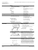
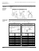
Selecting the
Direction of
Operation
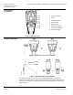
• With normally-closed valves, "direct-acting" means that with a 0 Vdc signal input, the valve
is closed.
• With Normally-open valves, "direct-acting" means that with a 0 Vdc signal input, the valve
is open.
Input:
0 to 10 Vdc
Input
10 to 0 Vdc
0 Vdc
10 Vdc
4 to 20 mA
20 to 4 mA
4 mA
20 mA
0 to 1000 ohm
1000 to 0 ohm
0 ohm
1000 ohm
Figure 14. Direction of Operation.
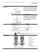
Sequence Control
or Stroke Limit
Control
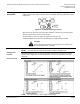
Check the wiring for proper connections.
NOTE: The valve body assembly determines the complete assembly action.
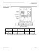
Table 3. Table 4.
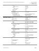
Setting the Stroke Limit Control
Setting the Sequence Control
The rotary switches LO and UP can be
used to apply an upper and lower limit
to the stroke in increments of 3% up to
a maximum of 45%.
The rotary switches LO and UP can be used
to determine the starting point (Start) or the
operating range of a sequence (Span).
Position
of
LO
Lower
Stroke
Limit
Position
of
UP
Upper
Stroke
Limit
Position
of
LO
Starting
Point for
Sequence
Control
Position
of
UP
Operating
Range of
Sequence
Control
0
0%
0
100%
0
0V
0
10V
1
3%
1
97%
1
1V
1
10V*
2
6%
2
94%
2
2V
2
10V*
3
9%
3
91%
3
3V
3
3V*
4
12%
4
88%
4
4V
4
4V
5
15%
5
85%
5
5V
5
5V
6
18%
6
82%
6
6V
6
6V
7
21%
7
79%
7
7V
7
7V
8
24%
8
76%
8
8V
8
8V
9
27%
9
73%
9
9V
9
9V
A
30%
A
70%
A
10V
A
10V
B
33%
B
67%
B
11V
B
11V
C
36%
C
64%
C
12V
C
12V
D
39%
D
61%
D
13V
D
13V
E
42%
E
58%
E
14V
E
14V
F
45%
F
55%
F
15V
F
15V
*The smallest adjustment is 3 Vdc; Control with 0 to
3 Vdc is possible only via Y.