
Data Sheet for Product
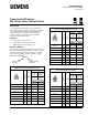
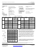
Table Of Contents

Powermite 599 Series, MZ Series Zone Control Valves Submittal Sheet
Document No. 154-012P25
April 9, 2009
Information in this publication is based on current specifications. The company reserves the right to make changes in specifications and models as design
improvements are introduced. Product or company names mentioned herein may be the trademarks of their respective owners.
© 2009 Siemens Industry, Inc.
Siemens Industry, Inc.
Building Technologies Division
1000 Deerfield Parkway
Buffalo Grove, IL 60089
+ 1 847-215-1000
Your feedback is important to us. If you have
comments about this document, please send them to
sbt_technical.editor.us.sbt@siemens.com
Document No. 154-012P25
Printed in the USA
Page 2 of 2
Technical Data
Line Size 1/2 to 1 inch (15 to 25 mm)
Body Globe style, UNS CA 844 bronze
or forged brass C37700, ANSI
Class 250
Trim Brass
Stem Stainless steel
ASTM A582 Type 303,
7/32-inch (5.5-mm) stroke
Seat Metal-to-metal
Packing Ethylene propylene O-ring
Mounting NEMA 1 (interior only)
Flow characteristics:
Two-way valves Modified equal percentage
Three-way valves Linear
Close-off Ratings According to ANSI/FCI 70-2
See Table 1.
Controlled Medium:
Two-way valves Water or water-glycol solutions to 50%
Three-way valves Water or water-glycol solutions to 50%
Medium Temperature 35°F to 250°F (2°C to 120°C)
Max. Differential Pressure
for Modulating Service:
Liquid (2w and 3w) 25 psi (173 kPa)
Rangeability Cv <1 = >50:1, Cv >1 = >100:1
Leakage Rate Class IV (0.01% of Cv)
Table 1. Close-Off Ratings.
Action
Line Size
Inches (mm)
Flow Rate,
Cv (Kvs)
Close-Off Ratings
psi (kPa)
Action
Line Size
Inches (mm)
Flow Rate,
Cv (Kvs)
Close-Off Ratings
psi (kPa)
Electronic Actuator
SSB…
Electronic Actuator
SSB…
NC 1/2 (15)
0.4 to 1.6
(0.34 to 1.37)
70 (483)
3-Way
Mixing,
upper
1/2 (15)
0.4 to 1.6
(0.34 to 1.37)
70 (483)
1/2 (15)
2.5 to 4
(2.15 to 3.44)
40 (276) 1/2 (15)
2.5 to 4
(2.15 to 3.44)
40 (276)
3/4 (20) and
1 (25)
6.3 to 10
(5.43 to 8.6)
30 (207)
3/4 (20) and
1 (25)
6.3 to 10
(5.43 to 8.6)
30 (207)
NO 1/2 (15)
0.4 to 1.6
(0.34 to 1.37)
60 (412) 3-Way
Mixing,
lower
1/2 (15)
0.4 to 1.6
(0.34 to 1.37)
25 (172)
1/2 (15)
2.5 to 4
(2.15 to 3.44)
35 (241) 1/2 (15)
2.5 to 4
(2.15 to 3.44)
15 (103)
3/4 (20) and
1 (25)
6.3 to 10
(5.43 to 8.6)
30 (207)
3/4 (20) and
1 (25)
6.3 to 10
(5.43 to 8.6)
10 (69)
Table 2. Valve Dimensions.
Typical Specifications
Automatic control valves shall have NPT threaded type
fittings, 1/2-inch through 1-inch (15 mm through 25 mm)
sizes, and shall be ANSI rate
d to withstand the pressures and
temperatures encountered. Valves shall have metal-to-metal
seats, stainless steel stems, and Ethylene propylene O-ring
packing. Valves shall be ANSI Leakage Class IV (0.01% of
Cv). Valves shall have a 50:1 rangeability (Cv <1) or better.
All two-way valves shall be provided with equal-percentage
contoured throttling plugs. All three-way valves shall be
provided with throttling plugs such that the total flow through
the valve remains constant (linear) regardless of the valve
position.
For complete technical details on two-way valves with union female,
angle female, or union male end connections, see Powermite
™ 599
Series, MZ Series Zone Control Unit Two-way Valves Technical
Instructions, Document No. 155-198P25.
2-Way Valve
Size
In.
(mm)
A
B
C
Weight
lbs. (kg)
1/2
(15)
1-3/8
(35)
2-1/4
(57)
1-5/16
(33)
.96
(.44)
3/4
(20)
1-5/8
(41)
2-3/8
(59)
1-5/16
(33)
1.13
(.51)
1
(25)
1-15/16
(49)
2-3/4
(69)
1-9/16
(39)
1.7
(.77)
3-Way Valve
1/2
(15)
2-3/4
(69)
2-1/4
(74)
1-5/16
(33)
1.10
(0.5)
3/4
(20)
3-1/4
(83)
3-9/16
(90)
1-5/16
(33)
1.44
(.65)
1
(25)
3-7/8
(98)
3-
15/16
(99)
1-9/16
(39)
2.20
(1.0)