
Installation Instructions


Installation Instructions
Document No. 129-228
September 29, 2009
Flowrite™ AP 599 Series
4-inch Pneumatic Valve Actuator
Item Number 129-228, Rev. 200 Page 1 of 4
Product Description
The Flowrite AP 599 Series 4-inch Pneumatic Valve
Actuator is designed for use with the Flowrite
VF 599 Series valves with a 3/4-inch (20 mm)
stroke.
Product Numbers
599-01081 3 to 8 psi (21 to 55 kPa) spring range
599-01082 5 to 10 psi (34 to 69 kPa) spring range
599-01083 10 to 15 psi (69 to 103 kPa) spring
range
Warning/Caution Notations
WARNING
Personal injury/loss of life may
occur if a procedure is not
performed as specified.
CAUTION
Equipment damage, or loss of
data may occur if the user
does not follow a procedure as
specified.
Required Tools
5 mm hex wrench
5/16-inch hex wrench
1/8-inch NPT straight barbed fitting
Squeeze bulb (baumanometer)
Expected Installation Time
16 minutes for field mounting of the actuator.
36 minutes for removing the old and mounting a new
actuator.
Prerequisites
WARNING:
If mounting the actuator to a valve already in
line, either close the shut-off valves in the
piping (upstream first, then downstream) or
switch off the pump to allow the differential
pressure to drop.
CAUTION:
Do not damage or scratch the polished
surface of the valve stem.
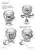
AP0216R1
Figure 1. Acceptable Mounting Positions.
The vertical position is recommended for mounting.
Figure 1 shows the acceptable mounting positions.
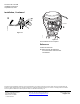
Installation
If you are not replacing an existing actuator, begin
with the instructions of Figure 5.