
Installation Instructions
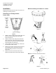
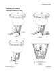
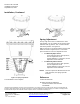
Table Of Contents

Document No. 129-184
Installation Instructions
September 25, 2009
Information in this publication is based on current specifications. The company reserves the right to make changes in specifications and
models as design improvements are introduced.
Flowrite is a registered trademark of Siemens Industry, Inc. Product or company names
mentioned herein may be the trademarks of their respective owners. © 2009 Siemens Industry, Inc.
Siemens Industry, Inc.
1000 Deerfield Parkway
Buffalo Grove, IL 60089-4513
U.S.A.
Tel. +1 847-215-1000
Your feedback is important to us. If you have
comments about this document, please send them to
sbt_technical.editor.us.sbt@siemens.com
Document No. 129-184
Printed in the U.S.A.
Page 4 of 4
Installation, Continued
Figure 10.
Figure 11.
Figure 12. Spring Adjustment.
The installation is now complete.
Spring Adjustment
The top edge of the stem nut indicates the valve
stem position. The “0” marking on the actuator yoke
indicates stem up position. The “1” mark indicates
stem down position. See Figure 12.
With the actuator in an upright position and the stem
visible as shown in Figure 12, use a 1-1/16 inch
open-end wrench to turn the adjustment screw.
• For Normally Open Valves:
To increase the start to close pressure,
turn the adjustment screw
counterclockwise. To decrease, turn the
adjustment screw clockwise.
• For Normally Closed Valves:
To increase the start to open pressure,
turn the adjustment screw
counterclockwise To decrease, turn the
adjustment screw clockwise.
NOTE: As the line pressure differential across the
valve increases, the spring span will
increase.
Reference
Technical Instructions
AP 599-2 Flowrite AP 599 Series
12-inch Pneumatic Valve Actuator
155-162P25