
User Guide

599 Series Zone Valve and Actuator Assembly Selection Technical Bulletin TB254
Document Number 155-291
August 17, 2005
Information in this publication is based on current specifications. The company reserves the right to make changes in specifications and models as
design improvements are introduced. Other product or company names mentioned herein may be the trademarks of their respective owners.
©2005 Siemens Industry, Inc.
Siemens Industry, Inc.
Building Technologies Division
1000 Deerfield Parkway
Buffalo Grove, IL 60089
+ 1 847-215-1000
Your feedback is important to us. If you have
comments about this document, please send them
to sbt_technical.editor.us.sbt@siemens.com
Document No. 155-291
Printed in the USA
Page 9
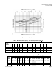
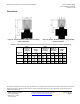
Dimensions
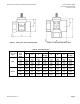
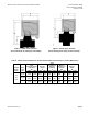
Figure 8. Thermic Actuator: 2-Way Valve Assembly
Service Envelope.
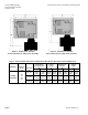
Figure 9. Thermic Actuator: 3-Way Valve Assembly
Service Envelope.
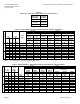
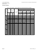
Table 10. STA/P Thermic Actuator Dimensions and Recommended Service Envelope in Inches (Millimeters).
Valve Line
Size
Valve
Centerline to
Top of
Actuator
H
1
Service
Height
H
Valve
Centerline to
Actuator
Coupling
C
Width or
Diameter of
Actuator
W
1
Service
Width
W
2-Way
3-Way
2-Way
3-Way
2-Way
3-Way
2-Way
3-Way
2-Way
3-Way
0.5 (15)
3.44
(87)
3.44
(87)
7.44
(189)
7.44
(189)
1.00
(25)
1.00
(25)
1.71
(43.5)
1.71
(43.5)
9.86
(251)
9.86
(251)
0.75 (20)
3.44
(87)
3.44
(87)
7.44
(189)
7.44
(189)
1.00
(25)
1.00
(25)
1.71
(43.5)
1.71
(43.5)
9.86
(251)
9.86
(251)
1.00 (25)
3.44
(87)
3.44
(87)
7.44
(189)
7.44
(189)
1.00
(25)
1.00
(25)
1.71
(43.5)
1.71
(43.5)
9.86
(251)
9.86
(251)