
Install Instructions

Technical Bulletin TB254 599 Series Zone Valve and Actuator Assembly Selection
Document Number 155-291
August 17, 2005
Page 2 Siemens Industry, Inc.
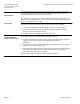
Selection Examples
In an ANSI 125 piping system, a two-way, normally closed, female-by-female, NPT
threaded valve delivers 6 gpm (0.52 m
3
/hr) chilled water with no more than 6-psi
(41.4 kPa) pressure drop across the fully open valve.
The actuator is to receive 120 Vac power; accept a two-position control signal, and
provide normally closed operation. The actuator closes off tightly against a pump head
pressure of 14.5 psi (100 kPa, 1 bar).
Specifications
Valve Sizing
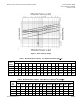
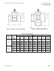
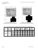
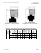
See Figure 1, the Water Capacity Graph, to select the valve size as follows:
1. Locate the required flow rate by finding gpm (m
3
/hr) on the vertical axis.
2. Follow across the horizontal axis and find the psi (kPa) maximum allowable
pressure drop across the open valve
.
3. Select the valve line size that will ensure proper flow
.
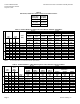
Assembly
(Product Number)
Selection: An Example
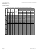
Use Table 4 to select a valve and actuator assembly as follows:
1. Read the table from left to right and select a NPT connection. Select a 0.50-inch
(15 mm), 2.5 Cv (2.0 Kvs) valve. The valve body part number is
599-00211.
2. Read across the top of the table and select a normally closed, 120 Vac actuator
prefix code. The prefix number is 240.
3. Read down the SFA11U actuator column and across the 0.50-inch (15 mm) valve
body row to select 240-00211. The column/row intersection determines the
appropriate valve and actuator assembly.
Alternatively, the valve and actuator can be ordered separately.