
User Guide


RL 147 Positioning Relay Technical Instructions
Document Number 155-038P25
April 1, 2005
Siemens Industry, Inc. Page 7
Calibration,
Continued
Adjusting the Span
1. Using the squeeze bulb, apply pressure to the relay. Note the pressure at which the
stem or shaft begins to move.
2. Continue to apply pressure until the stem or shaft completes its full stroke. Note the
pressure.
3. Check the difference between the two pressures; this is the span.
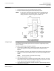
4. If the span is not the desired span, move the spring guide to a higher reference
number to increase the span or lower number to decrease the span. See Figure 4.
5. Repeat Steps 1 through 4 until you get the desired span.
6. If you have moved the spring guide, adjust the spring arm so that the spring is
parallel to the stem or shaft.
7. Check the feedback spring. There should be no slack or stretch in it. Adjust the wing
nuts and adjustment nut, if necessary.
8. Fasten the relay cover. Fill in the information on the calibration label.
Calculating the Span
Setting
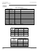
1. Identify the valve stem from Table 3 or 4. If the stroke of the No. 6 damper actuator
has been changed from the factory setting, see Table 7.
2. If your stem travel matches the nominal spring travel listed in Table 2, there is no
need to calculate a new span setting.
3. If your stem travel does not match the nominal spring travel listed in Table 2, choose
the spring(s) whose maximum allowable travel is equal or greater than your actual
stem travel.
4. Calculate the span setting with the following formula:
Formula for Span Setting
Span
Setting
= Desired span X Nominal spring travel
Actuator stroke
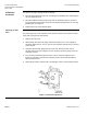
Example:
Determine the span setting for a valve having a
span of 5 psig and 5/16-inch stroke.
Select a spring with a maximum allowable range equal to or larger than the stroke.
Use the 1/4-inch spring with a 3/8-inch maximum allowable travel range.
See Table 2.
Span
Setting
= 5 X 0.25
0.312
= 4
Set the span adjustment tab to line 4 on the feed back arm to provide a 5 psig span
for this valve.