
User Guide


RL 147 Positioning Relay Technical Instructions
Document Number 155-038P25
April 1, 2005
Siemens Industry, Inc. Page 5
Calibration
Complete calibration instructions are included with each positioning relay.
1. Check that you have the correct feedback spring(s) attached.
2. Identify the desired operating span and the start point pressure.
NOTE: In some cases, the actuator stem travel or stroke is not identical to the
nominal value of the relay feedback spring. See Calculating the Span
Setting to determine the span setting on the feedback arm.
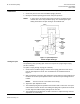
Figure 4. Span Adjustment.
Shown at Span Setting 8.
Setting the Span
See Figure 4.
The positioning relay operating span can be set for spans of 3 psig through 12 psig
(21 kPa to 83 kPa).
For spans of 3 psig through 10 psig (21 to 69 kPa):
1. Check that the feedback spring is attached to the spring guide in the hole across
from the span adjustment screw. This is identified as the standard location in
Figure 4.
2. With a screwdriver, loosen the span adjustment screw. Move the spring guide on the
feedback arm until the span adjustment tab is at the desired span setting reference
number.
NOTE: The line to the left of the number is the setting.
3. Tighten the span adjustment screw.
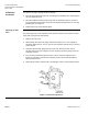
4. The feedback spring must be parallel to the actuator shaft or valve stem. Use open-
end wrenches to loosen the hex nuts holding the spring arm in position on the shaft
or stem. Align the feedback spring and tighten the hex nuts.
5. The feedback spring should have no slack or stretch in it. Adjust the wing nuts and
adjustment nut, if necessary.