
User Guide


RL 147 Positioning Relay Technical Instructions
Document Number 155-038P25
April 1, 2005
Siemens Industry, Inc. Page 3
Application,
Continued
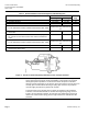
A positioning relay can be connected to handle up to four identical No. 6 damper
actuators or up to six identical No. 4 damper actuators if all actuators operate the same
damper, and no more than 100 feet of 1/4-inch (6.4 mm) OD tube is used to connect
them. All actuators connected this way must be identical (that is, same size, spring
range, stroke, etc.).
The positioning relay is single acting and is primarily intended for use on actuators with
an integral spring to return the actuator shaft to the normal position. Applications with a
double acting (springless) actuator require a reversing relay to provide the additional
control signal.
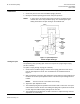
Operation
A rise in thermostat pressure will unbalance the lever assembly. See Figure 2. The shaft
movement, through the spring arm, increases tension on the feedback spring to bring
the lever assembly again into balance. A drop in thermostat pressure will unbalance the
lever assembly in the opposite direction to exhaust air from the actuator until a new
balance position is reached.
The positioning relay start point is adjustable. The start point adjustment nut shown in
Figure 2 is used to set the start point pressure. The span adjustment screw tab location
on the feedback arm and the feedback spring location on the spring guide determine the
span setting of the relay.
Figure 2. Operation Schematic.