
User Guide


RL 147 Positioning Relay Technical Instructions
Document Number 155-038P25
April 1, 2005
Siemens Industry, Inc. Page 13
Calibration,
Continued
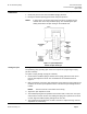
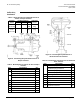
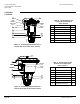
Figure 12. Positioning Relay Mounted on the
Flowrite 8-inch Actuator (Models 1 and 2)
and Super Flowrite.
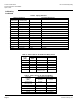
Table 13. Mounting Kit 147-277*
for Flowrite 8-inch Valve Actuator
Models 1 and 2.
Item Description Qty.
1 Mounting Bracket 1
Feedback Spring, Small Cadmium
Plate
2
2 Feedback Spring, Small Red 1
Feedback Spring, Large Green 1
Feedback Spring, Small Green 2
3 Adjusting Screw, 4-1/2" (114 mm) 1
4 Wing Nut 2
5 Lock Washer 1
6 Flat Washer 1
7 Spring Arm 1
8 Sure-tite Clamp 1
9 90° Elbow Connector 1
*Also order spring arm No. 147-307 for use with
VF 591 5-inch and 6-inch balanced valves.
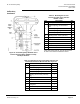
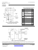
Table 14. Mounting Kit 147-279 for Super Flowrite and
12-inch Flowrite Before March 1978. See Figure 12.
Item Description Quantity
1 Mounting Bracket 1
Feedback Spring-Small Cad. Plate 2
2 Feedback Spring-Small Red 2
Feedback Spring-Large Green 1
3 Adjusting Screw-4-1/2" (114 mm)
long
1
4 Wing Nut 2
5 Lock Washer 1
6 Flat Washer 1
7 Spring Arm 1
8 Sure-Tite Clamp 1
9 90° Elbow Connector 1