
Install Instructions
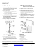
Table Of Contents

Document No. 129-199
Installation Instructions
September 28, 2009
Information in this publication is based on current specifications. The company reserves the right to make changes in specifications and
models as design improvements are introduced. Flowrite is a registered trademark of Siemens Industry, Inc. © 2009 Siemens Industry, Inc.
Siemens Industry, Inc.
Building Technologies Division
1000 Deerfield Parkway
Buffalo Grove, IL 60089-4513
U.S.A.
Tel. +1 847-215-1000
Your feedback is important to us. If you have
comments about this document, please send them to
sbt_technical.editorus.sbt@siemens.com
Document No. 129-199
Printed in the U.S.A.
Page 2 of 2
Installation, Continued
4. Position the spring arm (7) on the valve stem so
the slot for the adjusting screw (3) is in line with
the spring guide. Lock the spring arm in position
between the jam nut and the stem nut.
5. Do one of the following:
• If the valve has a 3/4-inch (20 mm) stroke,
use one feedback spring.
• If the valve has a 1-1/2 inch (40 mm) stroke,
use two feedback springs.
6. Connect the feedback spring(s) (2) between the
spring guide and the adjusting screw (3). If more
than one feedback spring is required, connect
them in a series end to end.
7. Thread one wing nut (4) onto the adjusting
screw (3). See Figure 2.
Figure 2. Attaching the Adjusting Screw to the
Spring Arm.
8. Slide the adjusting screw through the spring
arm. Thread the remaining wing nut onto the
adjusting screw. Tighten the wing nuts so that
there is no slack in the spring, but do not stretch
the spring.
NOTE: Adjust the spring arm so that the
adjusting screw and the feedback spring
are parallel to the actuator shaft.
9. Attach the connector (9) to the actuator. See
Figure 1.
10. Make pneumatic piping connections to the
actuator and relay. The “S” Port is the air supply
port. The “M” Port goes to the connector on the
actuator. The “T” Port is the signal from the
controller. See Figure 3.
11. Place the calibration label on the cover as
shown in Figure 3. Mark for reference. (Optional)
Attach the relay cover if you are not calibrating
immediately.
12. Calibrate the relay by following the instructions
included with the positioning relay.
Figure 3. Positioning Relay Ports.
Reference
Technical Instructions
Positioning Relay
155-038P25
Installation Instructions
Positioning Relay Calibration
129-125