
Install Instructions
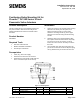
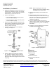
Table Of Contents

Installation Instructions
Document No. 129-199
September 28, 2009
Positioning Relay Mounting Kit for
Flowrite™ AP 599 Series 12-inch
Pneumatic Valve Actuators
Item Number 129-199, Rev. 200 Page 1 of 2
Product Description
This kit contains the RL 147 Positioning Relay and
the parts needed to field mount the relay on the
Flowrite AP 599 Series 12-inch Pneumatic Valve
Actuators.
Product Number
599-00423
Required Tools
• 9/16-inch socket wrench
• Medium flat-blade screwdriver
• 30 mm open-end wrench
Prerequisites
• Clean, dry, oil-free air supply
• Disconnect the air line to the actuator.
• Determine the valve stroke. It will either be
3/4 or 1-1/2 inches (20 mm or 40 mm)
Installation
1. Select two screws in the actuator upper housing
which are not directly over the yoke; use a
9/16-inch socket wrench to remove them.
Attach the mounting bracket (1) to the upper
housing of the actuator using the two housing
screws.
2. Attach the relay to the mounting bracket with
two captive screws furnished on the relay body.
For access to one of the screws, you must
loosen the cover screw on the relay to remove
the cover.
3. Use a 30 mm open-end wrench to loosen the
jam nut on the actuator stem and slip the spring
arm (7) between the jam nut and the stem nut.
Figure 1. Mounting Parts.
Item Description Q'ty Item Description Q'ty
1
Mounting bracket
1
4
Wing nut
2
2
Feedback spring
2
7
Spring arm
1
3
Adjusting screw
1
9
90° Elbow connector
1