
Data Sheet for Product


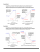

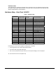

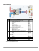
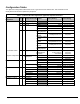
Table Of Contents
- Figure 1. Dual Duct VAV Box with Two Inlet Flow Sensors.
- Figure 2. Dual Duct VAV Box with One Inlet and One Discharge Flow Sensor.
- Features
- Sequence of Operation
- Dual Cold
- Dual Hot
- Morning Warm-up/ Pre-Cool
- Off
- Test/Calibrate
- Occupancy Control
- Special Features
- Hardware Map – Dual Duct VAV/CV
- Wiring Diagram
- Bill of Materials
- Configuration Tables
- Control Mode Interaction Table –Dual Duct VAV with QVM
- Control Mode Interaction Table –Dual Duct CV with QVM

Document No. 588-023 Page 7 of 13
Perimeter Heat
This application also supports the optional control of perimeter heat. The algorithm supports analog,
three-point floating, pulse width modulation, and on/off control of the perimeter heat. Perimeter heat
operates independently of terminal airflow.
Hardware Map – Dual Duct VAV/CV
Table 1. Hardware Map.
Termination
Set
Element Name I/O Type Factory I/O Setting
StatTemp statTemp TEMP SPACE_TEMP
StatSetpt statSetpt TEMP SPACE_STPT_TEMP
StatOvrd statOvrd DI STAT_SWITCH_DI
In1 in1 DI, TEMP SOURCE_TEMP
In2 in2 DI, TEMP SPARE1_TEMP
In3 in3 DI, PCT, TEMP WALL_SWITCH_DI
In4 in4 DI, PCT, TEMP OCC_SENSOR_DI
In5 in5 DI, PCT, TEMP VELOCITY_EXT2_PCT
In6 in6 DI, PCT, TEMP VELOCITY_EXT1_PCT
OutA1 outA1 AO FLOW_DMPR_AO
OutA2 outA2 AO FLOW_DMPR2_AO
OutA3 outA3 AO OUT_UNUSED
OutD1 outD1 DO, FLT_MTR FLOW_DMPR_FLT_MTR
OutD2 outD2 DO, FLT_MTR FLOW_DMPR_FLT_MTR
OutD3 outD3 DO, FLT_MTR FLOW2_DMPR_FLT_MTR
OutD4 outD4 DO, FLT_MTR FLOW2_DMPR_FLT_MTR
OutD5 outD5 DO, FLT_MTR PERIM_H_COIL_FLT_MTR
OutD6 outD6 DO, FLT_MTR PERIM_H_COIL_FLT_MTR
OutD7 outD7 DO, FLT_MTR OUT_UNUSED
OutD8 outD8 DO, FLT_MTR SPC_LIGHTS_DO
In1 through In6 can be used for digital or analog inputs, as follows:
• In1 through In6 are dry contact inputs (with resistors)
• In1 and In2 also accept 10K ohm inputs
• In3, In4, In5, and In6 also accept current (4 to 20 mA) and voltage (0 to 10 volt) inputs
A1, A2, and A3 are 0 to 10 volt outputs only.