
Datasheet


3RV Motor Starter Protectors/Circuit Breakers up to 100 A
7
Siemens · 2010
General data
■
Function
Trip units
3RV1 motor starter protectors are equipped with inverse-time
delayed overload release based on the bimetal principle and
with instantaneous electronic trip units (electromagnetic short-
circuit releases).
The overload releases can be adjusted in accordance with the
load current. The electronic trip units are permanently set to a
value 13 times the rated current and thus enable trouble-free
starting of motors.
Motor starter protectors for line-side transformer protection are
set to 20 times the rated current to prevent tripping as a result of
high transformer inrush current.
The scale cover can be sealed to prevent unauthorized adjust-
ments to the set current.
Trip classes
The trip classes of thermally delayed trip units are based on the
tripping time (t
A
) at 7.2 times the set current in cold state (ex-
cerpt from IEC 60947-4):
• CLASS 10A: 2 s < t
A
<10s
• CLASS 10: 4 s < t
A
<10s
• CLASS 20: 6 s < t
A
<20s
• CLASS 30: 9 s < t
A
<30s
The motor starter protector must trip within this time!
Operating mechanisms
S00 motor starter protectors are actuated by a rocker operating
mechanism and S0, S2 and S3 motor starter protectors by a ro-
tary operating mechanism. If the motor starter protector trips, the
rotary operating mechanism switches to the tripped position to
indicate this. Before the motor starter protector is reclosed, the
rotary operating mechanism must be reset manually to the 0 po-
sition. Only then can the motor starter protector be set again to
the I position.
In the case of motor starter protectors with rotary operating me-
chanisms, an electrical signal can be output by a signal switch
to indicate that the motor starter protector has tripped.
All operating mechanisms can be locked in the 0 position with a
padlock (shackle diameter 3.5 mm to 4.5 mm).
The motor starter protector isolating function complies with
IEC 60947-2.
■
Configuration
Prevention of unintended tripping
In order to prevent premature tripping due to the integrated
phase failure sensitivity, motor starter protectors should always
be connected to ensure current flows through all three main cur-
rent paths.
Short-circuit protection
If a short-circuit occurs, the short-circuit releases of 3RV1 motor
starter protectors isolate the faulty load feeder from the network
and thus prevent further damage.
Motor starter protectors with a short-circuit breaking capacity of
50 kA or 100 kA are virtually short-circuit resistant at a voltage of
400 V AC, since higher short-circuit currents are not to be ex-
pected in practice.
Motor protection
The tripping characteristics of 3RV10/3RV11 motor starter pro-
tectors are designed mainly to protect induction motors.
The motor starter protectors are therefore also referred to as
motor-protective circuit breakers
.
The rated current I
n
of the motor to be protected is set on the set-
ting scale. Factory setting of the short-circuit release is 13 times
the rated current of the motor starter protector. This permits
trouble-free starting and ensures that the motor is properly
protected.
The phase failure sensitivity of the motor starter protector en-
sures that it is tripped in time in the event of a phase failure and
overcurrents that occur as a result in the other phases.
Motor starter protectors with thermal overload releases are nor-
mally designed in accordance with trip class 10 (CLASS 10).
Motor starter protectors of sizes S2 and S3 are also available in
trip class 20 (CLASS 20) and therefore allow motors to be star-
ted up under arduous conditions.
Motor protection with overload relay function
(automatic RESET)
The 3RV11 motor starter protectors for motor protection with
overload relay function are designed for the protection of induc-
tion motors.
They are equipped with the same short-circuit release and over-
load release as motor starter protectors for motor protection
without overload relay function.
The motor starter protector always remains closed in the event
of an overload. The overload release activates only two auxiliary
contacts (1 NO + 1 NC). The overload trip can be signaled to a
higher-level control with the help of these auxiliary contacts. Ge-
nerally, it is also possible to open a downstream contactor
directly.
The overload signal is reset automatically. The motor starter pro-
tector itself only trips if a short-circuit occurs downstream.
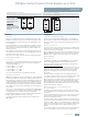
Standard mounting for S0, S2 and S3 Structure for S0 for the setting ranges
5.5 A ... 8 A up to 20 A ... 25 A for 690 V
NSB0_01069b
3RV1. ..
3RV1. ..
1L1 3L2 5L3 1L1 3L2 5L3
2T1 4T2 6T32T1 4T2 6T3
Wiring module
Size S0: 3RV19 15-1AB
Size S2: 3RV19 35-1A
Size S3: 3RV19 43-3D
Size S3 only:
Caution:
The wiring module
demands 10 mm spacing
between the motor starter
protectors
Line side
Load side
NSB0_01070a
3RV1. ..
3RV1. ..
1L1 3L2 5L3 1L1 3L2 5L3
2T1 4T2 6T32T1 4T2 6T3
Load side
Line side