
Datasheet


3RV Molded Case Motor Starter Protectors up to 800 A
49
Siemens · 2010
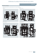
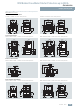
Accessories
Mountable accessories
■
Technical specifications
■
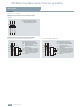
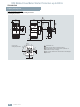
Schematics
Internal circuit diagrams
Circuit diagrams
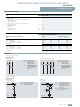
Auxiliary switches
Type 3RV19 91-1.A0
Rated operational current I
e
• At 250 V AC/DC
- At AC-14 (utilization category acc. to IEC 60947-5-1)
Supply voltage 125 V
Supply voltage 250 V
A
A
6
5
- At DC-14 (utilization category acc. to IEC 60947-5-1)
Supply voltage 125 V
Supply voltage 250 V
A
A
0.3
0.15
•At 24 V DC
- Supply voltage 24 V mA ≥ 0.75
- Supply voltage 5 V mA
≥ 1
Auxiliary trip units
Power consumption during pick-up
Molded case motor starter protectors
3RV13 53 3RV1. 6, 3RV1. 7, 3RV1. 83
Version
AC DC AC DC
Undervoltage trip units
3RV19 52-1A.0 3RV19 82-1A.0
• 24 ... 30 V AC/DC
1.5 VA 1.5 W 6VA 150 W
• 110 ... 127 V AC/110 ... 125 V DC
2VA 2W 6VA 150 W
• 220 ... 240 V AC/220 ... 250 V DC
2.5 VA 2.5 W 6VA 150 W
Opening times ms
15 15 ≤ 25 ≤ 15
Shunt trip units
3RV19 52-1E.0 3RV19 82-1E.0
• 24 ... 30 V AC/DC
50 VA 50 W 150 VA 150 W
• 110 ... 127 V AC/110 ... 125 V DC
50 VA 50 W 150 VA 150 W
• 220 ... 240 V AC/220 ... 250 V DC
50 VA 50 W 150 VA 150 W
Opening times ms
15 15 15 15
Auxiliary switches
3RV19 91-1AA0 3RV19 91-1BA0, 3RV19 91-1CA0
Auxiliary trip units
3RV19 .2-1A.0
Undervoltage trip unit
3RV19 .2-1E.0
Shunt trip unit
Indication of the
switch position of
the main contacts
Q1
Tripping indicated via
one of the protection
functions of the molded
case motor starter
protector
SY
Symbol acc. to IEC 6061712
11
NSB0_01985
Q1
14 96
95
SY
98
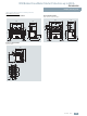
Indication of the
switch position of
the main contacts
Q1, Q2,
Q3
Tripping indicated via
one of the protection
functions of the molded
case motor starter
protector
SY
Symbol acc. to IEC 6061712
11
NSB0_01984
Q1
14 22
21
Q2
24 32
31
Q3
34 96
95
SY
98
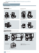
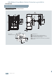
OFF button in the systemS1, S2
Undervoltage trip unitF4
Fuse (gL/gG), max. 10 AF1, F2
L1
N(L2)
F1
F2
D2
NSB0_00021b
D1
U
S1
S2
<F4
OFF button in the systemS0
Shunt trip unitF3
Motor starter protectorQ1
Auxiliary switch of the
molded case motor starter
protector Q1
S
Fuse (gL/gG), max. 10 AF1, F2
L1(L+)
N(L2,L-)
F1
F2
C2
NSB0_00020c
C1
S0
Q1
F3
12 14(14)
S 11(13)