
Datasheet


3RV Molded Case Motor Starter Protectors up to 800 A
General data
48
Siemens · 2010
■
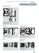
Schematics
Internal circuit diagrams
Molded case motor starter protectors with electronic trip unit
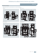
3RV13 53
Molded case motor starter protectors with electronic trip unit
TU 3: 3RV13 63, 3RV13 64, 3RV13 73, 3RV13 74, 3RV13 83 TU 4: 3RV10 63, 3RV10 73, 3RV10 83
L1 L2 L3
NSB0_01981
Q
Symbol according to IEC 60617
Auxiliary contacts of the molded
case motor starter protector
Q
L1 L2 L3
NSB0_01982
Q
TU 3
TI/L1
TI/L2
TI/L3
Y01
X0 1
X0 2
K51
Symbol according to IEC 60617
Electronic protection trip unitK51
Trip unitTU 3
Breaking coil of the solid-state
overcurrent trip unit
Y01
Plug-in connector for the Y01
breaking coil
X0
Current transformer on phase L1TI/L1
Current transformer on phase L2TI/L2
Current transformer on phase L3TI/L3
Auxiliary contacts of the molded
case motor starter protector
Q
L1 L2 L3
NSB0_01983
Q
TU 4
TI/L1
TI/L2
TI/L3
Y01
X0 1
X0 2
K51
Symbol according to IEC 60617
Electronic protection trip unitK51
Trip unitTU 4
Breaking coil of the solid-state
overcurrent trip unit
Y01
Plug-in connector for the Y01
breaking coil
X0
Current transformer on phase L1TI/L1
Current transformer on phase L2TI/L2
Current transformer on phase L3TI/L3
Auxiliary contacts of the molded
case motor starter protector
Q