
Datasheet


3RV Molded Case Motor Starter Protectors up to 800 A
41
Siemens · 2010
General data
■
Design
Installation guidelines for 3RV1 molded case motor starter protectors
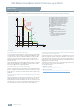
Installation clearances
When mounting the molded case motor starter protectors, the
following clearances must be maintained to grounded or live
parts and to cable ducts made of molded plastic.
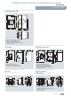
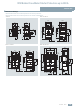
Minimum distance between two molded case motor starter protectors installed alongside or on top of each other
When molded case motor starter protectors are installed along-
side or on top of each other it is important to make sure that neit-
her the busbars nor connection cables reduce the clearance.
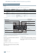
Minimum distance between two molded case motor starter protectors installed alongside each other
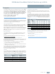
Minimum distance between two molded case motor starter protectors installed on top of each other
Note:
The quoted voltages apply for operational voltages U
b
up to
690 V. The mandatory distances must be added to the maximum
dimensions of the molded case motor starter protectors in their
various versions, including terminals.
Molded case motor starter protectors Mandatory distances
Type Rated operational voltage U
e
V
A
mm
B
mm
C
mm
3RV13 53
Up to 690
25 20 20
3RV1. 6.
Up to 400
440 ... 690
30
100
25 25
3RV1. 7.
Up to 400
440 ... 690
30
100
25 25
3RV1. 83
Up to 690
100 25 20
CA
B
NSB0_01977
Molded case motor starter protectors Mandatory distances
Type Rated operational
voltage U
e
V
Width
mm
Minimum distance
between axes l
mm
3RV13 53 Up to 690 90 90
3RV1. 6. Up to 690 105 105
3RV1. 7. Up to 440
500 ... 690
140 140
180
3RV1. 83 Up to 690 210 210
l
NSB0_01978
Y
Y
Y
Y
Molded case motor starter protectors Mandatory distances
Type Rated operational voltage U
e
V
Minimum distance
between axes H
mm
3RV13 53 Up to 690 90
3RV1. 6. Up to 690 160
3RV1. 7. Up to 690 160
3RV1. 83 Up to 690 180
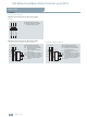
1
2
3
Non-insulated
connection
2
1
3
Insulated cable
Cable lug
H
H
H
NSB0_01979