
Datasheet

3RV Motor Starter Protectors/Circuit Breakers up to 100 A
29
Siemens · 2010
Accessories
Mountable accessories
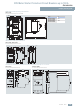
Circuit diagrams
Switching examples
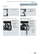
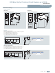
Undervoltage trip unit
3RV19 02-1A.., 3RV19 .2-1C..
Shunt trip unit
3RV19 02-1D.0
OFF button in the systemS1, S2
Undervoltage trip unitF4
Fuse (gL/gG), max. 10 AF1, F2
L1
N(L2)
F1
F2
D2
NSB0_00021b
D1
U
S1
S2
<F4
OFF button in the systemS0
Shunt trip unitF3
Motor starter protectorQ1
Auxiliary switch of the
molded case motor starter
protector Q1
S
Fuse (gL/gG), max. 10 AF1, F2
L1(L+)
N(L2,L-)
F1
F2
C2
NSB0_00020c
C1
S0
Q1
F3
12 14(14)
S 11(13)
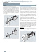
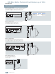
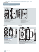
3RV1 motor starter protector with 3RV19 21-1M signal switch Motor starter protectors tripped by means of pushbutton or
EMERGENCY-STOP pushbutton in the system
v
v
v
F1
Signaling switch
Seperate "tripped" and
"short-circuit" signals
Motor starter protectorQ1
Signal lamp
"Short-circuit"
H1
Fuse (gL/gG)
max. 10 A
F1
Signal lamp
"Overload" or "Tripping
by auxiliary trip unit"
H2
S1
N
NSB0_00022c
L3
L2
H1
1
H2
Q1 S1
35
246
57 65 77 85
58 66 78 86
L1
v
v
v
S1
S2
S3
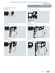
U <
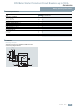
OFF pushbutton
The leading auxiliary
contacts will open in
switch position "OFF" to
deenergize the coil of
the undervoltage
release, thus avoiding
power consumption in
the switched off state.
Motor starter
protector
Q1
Undervoltage
trip unit
F4
Fuse (gL/gG)
max. 10 A
F1, F2
S1, S2, S3
In the "tripped" position
of the motor starter
protector, these contacts
are not guaranteed to
open.
N
NSB0_00023b
L3
L2
1
Q1 F4
F1
35
246
D1 07
D2 08
L1
F2