
Datasheet


3RV Motor Starter Protectors/Circuit Breakers up to 100 A
Accessories
Mountable accessories
26
Siemens · 2010
■
Overview
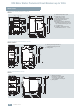
Mounting location and function
The 3RV1 motor starter protectors/circuit breakers have three
main contact elements. In order to achieve maximum flexibility,
auxiliary switches, signal switches, auxiliary trip units and
isolator modules can be supplied separately.
These components can be fitted as required on the circuit
breakers/motor starter protectors without using tools.
For overview graphic see "General Data" --> "Overview".
For a complete overview of which accessories can be used for
the various motor starter protectors see "Introduction"
--> "Overview" --> "Motor Starter Protectors".
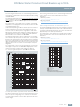
Front side
Notes:
• A maximum of 4 auxiliary contacts with
auxiliary switches can be attached to each
motor starter protector.
• Transverse auxiliary switches must not be
used for the 3RV17 and 3RV18 circuit brea-
kers.
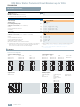
Transverse auxiliary switches
1NO+1NC
or
2NO
or
1 CO contact
An auxiliary switch block can be inserted transversely on the front. The over-
all width of the motor starter protectors remains unchanged.
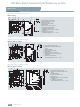
Left-hand side
Notes:
• A maximum of 4 auxiliary contacts with
auxiliary switches can be attached to each
motor starter protector/circuit breaker.
• Auxiliary switches (2 contacts) and signal
switches can be mounted separately or
together.
• The signal switch cannot be used for the
3RV17 and 3RV18 circuit breakers.
Lateral auxiliary switches
(2 contacts)
1NO+1NC
or
2NO
or
2NC
One of the three auxiliary switches can be mounted laterally for each motor
starter protector/circuit breaker. The contacts of the auxiliary switch close
and open together with the main contacts of the motor starter protector.
The overall width of the lateral auxiliary switch with 2 contacts is 9 mm.
Lateral auxiliary switches
(4 contacts)
2NO+2NC
One auxiliary switch can be mounted laterally for each motor starter protec-
tor. The contacts of the auxiliary switch close and open together with the
main contacts of the motor starter protector/circuit breaker.
The overall width of the lateral auxiliary switch with 4 contacts is 18 mm.
Signal switches for
sizes S0, S2 and S3
Tripping 1NO+1NC
Short-circuit 1 NO + 1 NC
One signal switch can be mounted at the side of each motor starter protector
with a rotary operating mechanism.
The signal switch has two contact systems.
One contact system always signals tripping
irrespective of whether this was
caused by a short-circuit, an overload or an auxiliary trip unit. The other con-
tact system only switches in the event of a short-circuit. There is no signaling
as a result of switching off
with the handle.
In order to be able to switch on the motor starter protector again after a
short-circuit, the signal switch must be reset manually after the error cause
has been eliminated.
The overall width of the signal switch is 18 mm.
Right-hand side
Notes:
• One auxiliary trip unit can be mounted per
motor starter protector/circuit breaker.
• Accessories cannot be mounted at the
right-hand side of the 3RV11 motor starter
protectors with overload relay function.
Auxiliary trip units
Shunt trip units
For remote-controlled tripping of the motor starter protector/circuit breaker.
The trip unit coil should only be energized for short periods
(see schematics).
or
Undervoltage trip units
Trips the motor starter protector when the voltage is interrupted and prevents
the motor from being restarted accidentally when the voltage is restored.
Used for remote-controlled tripping of the circuit breaker/motor starter
protector.
Particularly suitable for EMERGENCY-STOP disconnection by way of the cor-
responding EMERGENCY-STOP pushbutton according to EN 60204-1.
or
Undervoltage trip unit with
leading auxiliary contacts
(2 NO)
Function and use as for the undervoltage trip unit without leading auxiliary
contacts, but with the following additional function: the auxiliary contacts will
open in switch position OFF to deenergize the coil of the undervoltage trip
unit, thus interrupting energy consumption. In the "tripped" position, these
auxiliary contacts are not guaranteed to open. The leading contacts permit
the motor starter protector/circuit breaker to reclose.
The overall width of the auxiliary trip unit is 18 mm.
Top
Notes:
• The isolator module cannot be used for the
3RV17 and 3RV18 circuit breakers.
• The isolator module covers the terminal
screws of the transverse auxiliary switch. If
the isolator module is used, we therefore re-
commend that either the lateral auxiliary
switches be fitted or that the isolator modu-
le not be mounted until the auxiliary switch
has been wired.
Isolator modules for
sizes S0 and S2
Isolator modules can be mounted to the upper terminal end of motor starter
protectors of sizes S0 and S2.
The supply cable is connected to the motor starter protector through the iso-
lator module.
The plug can only be unplugged when the motor starter protector is open
and isolates all 3 poles of the motor starter protector from the network. The
shock-protected isolation point is clearly visible and secured with a padlock
to prevent reinsertion of the plug.