
Datasheet


3RV Motor Starter Protectors/Circuit Breakers up to 100 A
General data
22
Siemens · 2010
■
Dimensional drawings
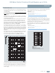
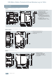
3RV1 motor starter protectors, size S00
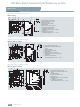
3RV1 motor starter protectors, size S0
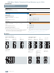
3RV1 motor starter protectors, size S2
3RV10 11, 3RV16
3RV10 21, 3RV13 21, 3RV14 21
1) 9) 3) 4)6)
8)
NSB0_00026d
45
90
70
76
918
62
5
45
12
45
3,5
7)
2)
18
25
5
105
5)
1) Lateral auxiliary switch, 2-pole.
2) Lateral auxiliary switch, 4-pole.
3) Auxiliary releases.
4) Transverse auxiliary switch.
5) Drilling pattern.
6) Push-in lugs for screw mounting.
7) Only for undervoltage release
with leading auxiliary switch.
8) Standard mounting rail TH 35 according
to EN 60715.
9) Lockable in neutral position
with shackle diameter 3.5 mm ... 4.5 mm.
8)
2)
6)
4)
7)
3)
1)
NSB0_00027c
45
14
12
90
97
45 5
56
80
91
45
69
18 18
72
9
5
25
106
5)
1) Lateral auxiliary switch, 2-pole.
2) Signal switch or lateral auxiliary switch,
4-pole.
3) Auxiliary releases.
4) Transverse auxiliary switch.
5) Drilling pattern.
6) Push-in lugs for screw mounting.
7) Standard mounting rail TH 35 according
to EN 60715.
8) Lockable in neutral position
with shackle diameter 3.5 mm ... 4.5 mm.
3RV10 31, 3RV13 31, 3RV14 31
20
5518
18
45
85
109
121
127
5
8
132
144
140
90
125
1) 2)
3)
4)
6)
NSB0_00028b
7)
9
5
30
130
5)
12
1) Lateral auxiliary switch, 2-pole.
2) Signal switch or lateral auxiliary switch,
4-pole.
3) Auxiliary releases.
4) Transverse auxiliary switch.
5) Drilling pattern.
6) Standard mounting rail TH 35 according
to EN 60715.
7) Lockable in neutral position
with shackle diameter 3.5 mm ... 4.5 mm.