
Datasheet

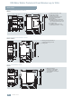


3RV Motor Starter Protectors/Circuit Breakers up to 100 A
General data
20
Siemens · 2010
Voltage transformer circuit breakers
1) If two different conductor cross-sections are connected to one clamping
point, both cross-sections must lie in the range specified. If identical
cross-sections are used, this restriction does not apply.
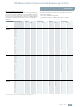
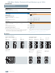
Rated data of the auxiliary switches and signal switches
Type 3RV19 Lateral auxiliary
switch with
1NO + 1NC, 2NO,
2 NC, 2 NO + 2 NC
Signal switches
Transverse auxiliary switches with
1 CO contact 1 NO + 1 NC, 2 NO
Max. rated voltage
Acc. to NEMA (UL) V AC 600 250
Acc. to NEMA (CSA) V AC
600 250
Uninterrupted current A
10 5 2.5
Switching capacity
A600
Q300
B600
R300
C300
R300
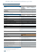
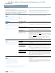
General technical specifications
Type 3RV16 11-1AG14 3RV16 11-1CG14 3RV16 11-1DG14
Rated current I
n
A 1.4 2.5 3
Ambient temperature
• During storage/transport °C –50 ... +80
• During operation °C
–20 ... +60 (up to +70 °C is possible with current reduction)
Rated operational voltage U
e
V 400
Rated frequency Hz
16.66 ... 60
Rated insulation voltage U
i
V690
Short-circuit breaking capacity I
cu
at 400 V AC kA 50
Set value of the thermal overload release A
1.4 2.5 3
Response value of the instantaneous electronic trip unit A
6 ± 20 % 10.5 ± 20 % 20 ± 20 %
Tripping time of the instantaneous electronic trip unit ms
Approx. 6 at 12 A Approx. 6 at 20 A Approx. 6 at 40 A
Internal resistance
• In cold state Ω >0.25± 6.5 %
• In heated state Ω
>0.30± 6.5 %
Shock resistance acc. to IEC 68 Part 2-27 g
15
Degree of protection acc. to IEC 60529
IP20
Touch protection acc. to EN 50274
Finger-safe
Endurance
• Mechanical Opera-
ting
cycles
10000
• Electrical Opera-
ting
cycles
10000
Permissible mounting positions
Any
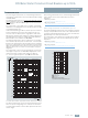
Type 3RV16 11-1AG14 3RV16 11-1CG14 3RV16 11-1DG14
Conductor cross-sections, main circuit, 1 or 2 conductors
Connection type Screw terminals
Terminal screw
Pozidriv size 2
Conductor cross-sections
• Solid mm
2
2 x (0.5 ... 1.5)
1)
, 2 x (0.75 ... 2.5)
1)
, max. 4
• Finely stranded with end sleeve mm
2
2 x (0.5 ... 1.5)
1)
, 2 x (0.75 ... 2.5)
1)
•Stranded mm
2
2 x (0.5 ... 1.5)
1)
, 2 x (0.75 ... 2.5)
1)
, max. 4
Auxiliary switch for blocking the distance protection
• With defined time-related assignment for blocking a distance relay 1 changeover contact (for use as 1 NO or 1 NC)
• Rated operational voltage U
e
(AC voltage) V 250
• Rated operational current I
e
/AC-14 at U
e
= 250 V A 0.5
• Rated operational current I
e
/AC-14 at U
e
= 125 V A 1
• Rated operational voltage U
e
(DC voltage L/R 200 ms) V 250
• Rated operational current I
e
/DC-13 at U
e
= 250 V A 0.27
• Rated operational current I
e
/DC-13 at U
e
= 125 V A 0.44
Short-circuit protection for auxiliary circuit
• Melting fuse gL/gG A 10
• Miniature circuit breaker, C characteristic A
6 (prospective short-circuit current < 0.4 kA)
Auxiliary switches for other signaling purposes
For technical specifications see "Mountable Accessories"