
Datasheet

3RV Motor Starter Protectors/Circuit Breakers up to 100 A
15
Siemens · 2010
General data
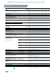
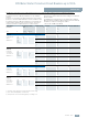
Footnotes for page 14:
1) For 3RV16 voltage transformer circuit breakers see more
"Technical specifications".
2) Above +60 °C current reduction.
3) 500 V with molded-plastic enclosure.
4) Terminal compartment IP00 (exception: 3RV10 11-..2. motor starter
protectors with Cage Clamp terminals degree of protection IP20).
5) With appropriate accessories.
Footnotes for page 15:
1) Cable lug and busbar connection possible after removing the box
terminals.
2) If bars larger than 12 mm x 10 mm are connected, a 3RT19 46-4EA1
terminal cover is needed to comply with the phase clearance.
3) If conductors larger than 25 mm
2
are connected, a 3RT19 46-4EA1
terminal cover is needed to comply with the phase clearance.
4) If two different conductor cross-sections are connected to one clamping
point, both cross-sections must lie in the range specified. If identical
cross-sections are used, this restriction does not apply.
5) For corresponding 8WA2 803 or 8WA2 880 opening tools
see Catalog LV 1, Chapter 5 "Protection Equipment" -->
"3RV Motor Starter Protectors up to 100 A" --> "Accessories".
6) With conductor cross-sections of ≤ 1mm
2
an "insulation stop" must be
used (see Catalog LV 1, Chapter 3, "Accessories and Spare Parts".
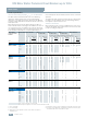
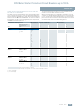
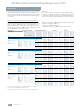
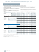
Conductor cross-sections of main circuit
Type 3RV1. 3RV1. 2 3RV1. 3 3RV1. 4/
3RV17 42
3RV17 21,
3RV18 21
Connection type
Screw terminals Screw terminals
with box terminal
Terminal screw
Pozidriv size 2 Pozidriv size 2 4 mm Allen screw Pozidriv size 2
Prescribed tightening torque Nm
0.8 ... 1.2 2...2.5 3 ... 4.5 4...6 2.5 ... 3
Conductor cross-sections
(1 or 2 conductors connectable)
• Solid mm
2
2 x (0.5 ... 1.5)
4)
,
2 x (0.75 ... 2.5)
4)
2 x (1 ... 2.5)
4)
,
2 x (2.5 ... 6)
4)
2 x (0.75 ... 16) 2 x (2.5 ... 16) 1...10,
max. 2 x 10
• Finely stranded with end sleeve mm
2
2 x (0.5 ... 1.5)
4)
,
2 x (0.75 ... 2.5)
4)
2 x (1 ... 2.5)
4)
,
2 x (2.5 ... 6)
4)
2 x (0.75 ... 16),
1 x (0.75 ... 25)
2 x (2.5 ... 35),
1 x (2.5 ... 50)
1...16,
max. 6 + 16
•Stranded mm
2
2 x (0.5 ... 1.5)
4)
,
2 x (0.75 ... 2.5)
4)
2 x (1 ... 2.5)
4)
,
2 x (2.5 ... 6)
4)
2 x (0.75 ... 25),
1 x (0.75 ... 35)
2 x (10 ... 50),
1 x (10 ... 70)
1.5 ... 25,
max. 10 + 25
• AWG cables, solid or stranded AWG
2 x (18 ... 14) 2 x (14 ... 10) 2 x (18 ... 2),
1 x (18 ... 2)
2 x (10 ... 1/0),
1 x (10 ... 2/0)
2 x (14 ... 10)
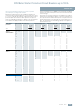
Ribbon cable conductors (number x width x thickness) mm
-- 2 x (6 x 9 x 0.8) --
Removable box terminals
1)
• With copper bars
2)
-- -- 18 x 10 --
• With cable lugs
3)
-- -- Up to 2 x 70 --
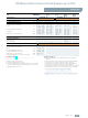
Connection type
Cage Clamp terminals
5)6)
Conductor cross-sections
(1 or 2 conductors connectable)
• Solid mm
2
2 x (0.25 ... 2.5) --
• Finely stranded with end sleeve mm
2
2 x (0.25 ... 1.5) --
• Finely stranded without end sleeve mm
2
2 x (0.25 ... 2.5) --
• AWG cables, solid or stranded AWG
2 x (24 ... 14) --
Max. external diameter of the conductor insulation mm
3.6