
Technical data


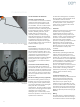
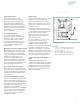

Primary disconnects
The cubicle stationary primary
disconnect contacts are recessed
inside the insulator assemblies, and
are located behind grounded steel
shutters to prevent accidental contact
when the circuit breaker is withdrawn.
The primary disconnect finger clusters
are mounted on the circuit breaker for
ease of inspection.
Secondary disconnects
The cubicle mounted stationary
disconnect contacts mate with spring
loaded secondary contacts on top of
the circuit breaker. The secondary
disconnects automatically engage in
both the test and connected positions,
and they remain engaged between
these positions.
Mechanism operated cell (MOC) switch
When required, up to 24 stages of the
MOC auxiliary switch can be mounted in
the circuit breaker cell. All spare MOC
contacts are wired to accessible terminal
blocks for user connections. As a
standard, these MOC switches are
operated only when the circuit breaker is
in the connected position. Optionally,
they may be arranged to operate in both
the connected and test positions.
Truck operated cell (TOC) switch
When required, up to 12 stages of the
TOC switch can be mounted in the circuit
breaker cell. All spare TOC contacts are
wired to accessible terminal blocks for
user connections.
Unobstructed terminal block space
Terminal block areas are located on each
side of circuit breaker or auxiliary cells.
Since racking system components are not
mounted on the cubicle sides, the side-
mounted terminal blocks are not
obstructed as in other designs.
Installation of field wiring is simplified, as
wiring can be easily laid directly against
the side sheets. It is not necessary to
“fish” the wiring under, around and
through obstructions.
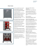
Auxiliary cells
Auxiliary cells are constructed in a similar
manner as the circuit breaker cells,
except without provisions for a circuit
breaker element. Auxiliary cells may be
located in the upper cell or lower cell of
a vertical section.
The front door panels may be used to
mount meters, protective relays or other
instrumentation. The interior portion of
the cell may be used for mounting
devices, such as VTs, CPTs (lower cell
only), automatic transfer switches or
other auxiliary devices.
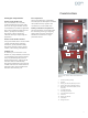
For ease in operation, primary current
limiting fuses for CPTs and VTs are
arranged in a drawout configuration,
while the heavy transformers are
stationary. This greatly reduces the effort
required to isolate transformers for
inspection or maintenance. The racking
mechanism for the drawout fuse truck is
manually operated with the compartment
door open, but it is otherwise similar to
the circuit breaker racking mechanism.
Auxiliary cell relay and instrument
space
The front panel of auxiliary cells is
suitable for mounting devices. Even if the
auxiliary cell contains rollout tray devices
(rollout fuses for VTs or CPTs), the space
available allows for mounting any of the
devices commonly specified for use on
metal-clad switchgear.
9
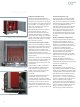
Figure 6: Auxiliary cells
Footnotes:
1. For VTs or rollout fuses for a CPT located
in lower cell, or for fan if 3,000 A circuit
breaker in lower cell
2. For circuit breaker, VTs, rollout fuses
for CPT located in rear or remote, or CPT
when rollout fuses located in upper cell.
1
2
Construction