
Technical data


Circuit breaker cell features
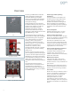
Vacuum circuit breaker cell
A circuit breaker cell consists of a bolted,
reinforced sheet steel enclosure, with
provisions for a type 38-3AH3 vacuum
circuit breaker. The cell includes a blank
hinged front door, inter-compartment
and inter-unit barriers, stationary primary
and secondary disconnects, automatic
shutters, drawout guide rails, circuit
breaker racking mechanism and
necessary interlocks. Control wiring,
terminal blocks and CTs are provided as
needed for the application. Instruments
and protective relays are mounted as
needed on the front panel of the upper
cell. Secondary control circuit cutouts are
located inside the upper cell.
Floor rollout
Circuit breakers in the lower cell can be
rolled out directly on the floor in front of
the unit without a handling device, lift
truck or hoist for indoor (if not on raised
“housekeeping” pad) and Shelter-Clad
installations. A lift truck accessory is
optionally available for handling drawout
primary fuse trucks in upper cells, or
circuit breakers in non-walk-in outdoor
enclosures.
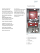
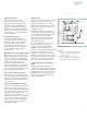
Closed door circuit breaker racking
The circuit breaker can be racked in or
out with the cell door open or closed. The
mechanism includes an indicator to show
the racking mechanism position with the
door closed. For racking, a manual drive
crank or an optional electric motor drive
may be used.
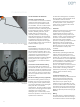
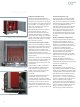
Electrical racking accessory (optional)
An electrical racking motor accessory is
available. This consists of a motor drive
assembly, which installs (without tools)
on mounting brackets on the switchgear
front panel of a circuit breaker
compartment. The unit includes a power
cord, which can be plugged into a duplex
receptacle in the vicinity of the
switchgear, plus a control cable, which
allows the operator to control the racking
operation from a distance.
An alternative arrangement is available,
which includes a control box that can be
mounted at a distance from the
switchgear and permanently connected
to control power. In turn, the racking
motor can be connected to the control
box with a long cord.
Interlocks
Interlocks prevent moving a closed circuit
breaker in the cell by preventing
engagement of the racking crank (or
electric racking accessory) if the circuit
breaker is closed. A second interlock lever
holds the circuit breaker mechanically
and electrically trip-free between
positions. The racking mechanism can be
padlocked to restrict unauthorized
racking of the circuit breaker. Separate
padlock provisions may be used to hold
the circuit breaker in the trip-free
condition.
Automatic shutters
Automatically operated grounded steel
shutters allow or block access to the
stationary primary disconnects in circuit
breaker cells. The shutters are opened by
the circuit breaker as it moves toward the
connected position. The shutters close as
the circuit breaker is racked away from
the connected position to the test
position. The shutters remain closed until
they are forced open by insertion of the
circuit breaker. This design enhances
protection for personnel, as compared to
shutters, which link to the racking
mechanism.
Current transformers (CTs)
Front-access CTs may be mounted around
both the upper and lower stationary
primary disconnect bushings. Up to a
total of four CTs per phase may be
located in each circuit breaker cell, two
on the bus side and two on the load side,
around the primary disconnect bushings.
The CTs may be standard accuracy (type
MD38) or optional special accuracy (type
MDD38).
Wiring
Secondary wiring is neatly bundled and
secured on the sides of the cell. Wiring is
not routed on the floor of the switchgear.
Construction
8
Figure 4: Circuit breaker being racked out with door
closed
Figure 5: Electrical racking accessory mounted on the
switchgear