
Technical data


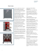


Structural flexibility
Siemens type GM38 metal-clad
switchgear provides enhanced flexibility
in locating circuit breaker, auxiliary and
metering cells within the structure layout.
Circuit breakers are located in the lower
cell positions. The upper cell position can
be used for voltage transformers with the
associated drawout primary fuses.
Each vertical section contains the main
bus bar compartment, plus a rear
compartment for incoming and outgoing
connections. The front portion of the
vertical section contains an upper cell for
auxiliary devices, VTs or drawout primary
fuses for a control power transformer
(CPT) located in the lower cell.
The front portion of the vertical section
contains a lower cell for circuit breaker,
auxiliary devices, VTs, CPT (if primary
fuses are located in upper cell) or
drawout primary fuses for a CPT located
in the rear of the section.
Circuit breaker cells include primary and
secondary disconnects, current
transformers (CTs) and secondary wiring,
as necessary. Instruments, protective
relays and power meters along with their
secondary wiring and other components
are located in the upper cell. The
switchgear is normally designed so that
additional vertical sections may be added
in the future.
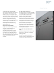
Enclosure design
The type GM38 design includes full ANSI/
IEEE C37.20.2 metal-clad construction.
This means complete enclosure of all live
parts and separation of major portions of
the circuit to retard the spread of faults to
other compartments. Removable plates
permit access to all compartments. The
rear panels are removable to allow access
to outgoing cable connections.
The structure is constructed of bolted
steel for better dimensional control than
with welded designs. Sheet steel inter-
unit barriers extend the full height and
depth of each vertical section for
isolating adjacent sections. The ground
bus extends the entire length of the
complete switchgear lineup and to each
circuit breaker cell.
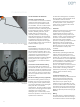
Circuit breaker interchangeability
The type GM38 switchgear cubicle and
the drawout type 38-3AH3 circuit breaker
element are both built to master fixtures,
so circuit breakers of the same ratings are
interchangeable with each other even if
the circuit breaker is required for use with
a cell with “provisions only” supplied
years earlier. The type 38-3AH3 circuit
breaker is interchangeable with the type
38-3AF circuit breaker, provided the
ratings are equal. The type 38-3AF circuit
breaker is not interchangeable with the
40 kA type 38-3AH3.
A circuit breaker of higher rating can be
used in a cell of equal or lower rating,
i.e., a 2,000 A 40 kA type 38-3AH3 circuit
breaker can be used in a 1,200 A 31.5 kA
type 38-3AH3 or type 38-3AF circuit
breaker cell.
Tested to ANSl/IEEE standards
Siemens type GM38 switchgear is tested
to meet the requirements of ANSl/IEEE
standards. A complete design test
program, including short-circuit
interruption, load-current switching,
continuous current, mechanical
endurance, close and latch current, short-
time and momentary withstand, impulse
withstand and the other tests required by
the standards, has been successfully
completed.
These tests encompass the complete
equipment design, including both the
switchgear structure and the circuit
breaker removable element. Production
tests in accordance with ANSl/IEEE
standards are performed on every group
of switchgear and on each circuit breaker.
Certified copies of test data can be
furnished to customers upon request.
The switchgear is not classified as arc-
resistant switchgear and has not been
tested for resistance to internal arcing per
ANSI/IEEE C37.20.7. Qualification to
seismic requirements of various codes
(for instance, IBC-2006, UBC, IEEE 693,
etc.) is available. Consult your local
Siemens representative with detailed
requirements.
UL or C-UL Listing available
When specified, if the component
configuration allows, the switchgear
rated 40 kA can be provided with the UL
or C-UL (for use in Canada) Listed label,
indicating conformance to the
requirements of ANSl/IEEE C37.54 and
ANSI/IEEE C37.55.
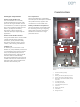
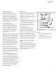
Overview
6
1. Drawout primary CL fuses for VTs
2. VTs (stationary)
3. Upper door for protective relays,
instruments, etc.
4. Type 38-3AH3 vacuum circuit breaker
5. Lower door (blank)
6. Copper main bus 1,200 A, 2,000 A or
3,000 A self-cooled
7. Power cable termination area
8. CTs
1
2
3
4
5
6
7
8
8
Figure 2: Circuit breaker cell (1,200 A or 2,000 A)
with VT auxiliary (3,000 A similar except upper
cell reserved for fan-cooling equipment)