
Technical data


Voltage transformers (VTs)
Up to three VTs with their drawout
mounted current limiting fuses may be
mounted in an auxiliary cell. VTs can be
accommodated in the upper cell above a
circuit breaker, or in either the upper or
lower cells of a section that does not
have a circuit breaker cell.
When the drawout fuses are moved to
the disconnect position, they are
automatically disconnected, and the
transformer windings are grounded to
remove any static charge. An insulating
shutter is provided, arranged to operate
before primary fuses become accessible
for inspection or removal.
Control power transformers (CPTs)
CPTs can be accommodated in either of
two manners. For single-phase and small
three-phase transformers, the primary
drawout fuses can be located in the
upper auxiliary cell of a vertical section,
and the fixed-mounted CPT can be
located in the lower front cell of the same
vertical section.
Alternatively, the primary drawout fuses
can be located in the lower auxiliary cell
of a vertical section, and the fixed-
mounted CPT can be located in the rear
of the section.
The secondary molded case breaker is
interlocked with the drawout primary
fuses so that the secondary circuit
breaker must be open before the CPT
primary can be disconnected or
connected.
This prevents accidental load-current
interruption on the main primary
contacts. With the secondary molded
case breaker open and the latch released,
the primary fuse truck can be moved
easily to the disconnect position. The
operation of the drawout fuse truck and
insulating shutter is similar to that for the
V Ts.
Current transformers (CTs)
Siemens toroidal CTs comply with ANSI/
IEEE standards and are mounted at the
rear of the circuit breaker cell. Up to four
standard accuracy type MD38 or special
accuracy type MDD38 CTs may be
mounted on each phase: two on the bus
side and two on the load side around
the primary disconnect bushings. CTs
may be added or changed with the cell
de-energized without removing bus bar
or cable connections. Multi-ratio CTs are
available.
Primary termination compartment
The primary termination compartment at
the rear of the switchgear section is
separated from all other compartments
by barriers. This space can be used for
connecting power cables, bus duct or for
connection to an adjacent power
transformer (PT). Surge arresters may
also be provided in this compartment.
Bolted rear plates are provided as
standard to provide access to the cable
area for each unit. Hinged rear doors are
available as an option.
Infrared (IR) viewing windows are
optionally available for use in checking
temperature of conductors in the primary
termination compartment.
Bus bar system
Full-round-edge copper bus bar with
silver-plated joints is standard. Tin-plated
copper bus is available as an option. High
strength grade 5 steel hardware with split
lock washers assures constant pressure,
low-resistance connections. A 0.25 in.
(6 mm) x 2.0 in. (51 mm) copper ground
bus bar is standard in all vertical sections
and is accessible at each end of the
lineup and in the primary termination of
each section. The main bus is available in
1,200 A, 2,000 A or 3,000 A self-cooled
ratings. The main bus bar system is
enclosed by grounded metal barriers.
Construction
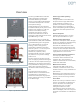
10
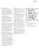
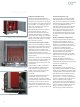
Figure 7: Primary CL fuses accessible when fuse truck
in disconnect position and access door open
Figure 8: VT cell with fuse truck withdrawn (shutter
closed, VT primaries grounded)
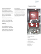
Figure 9: Fuse truck on extension rails