
User Guide


Technical Instructions Flowrite 599 Series Two-Way Valves
Document Number 155-184P25
July 23, 2008
Page 12 Siemens Building Technologies, Inc.
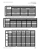
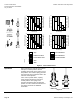
Dimensions
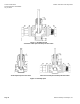
Figure 6. Dimensions.
The letters in Figure 6 refer to actuator and service envelope dimensions in Table
11. See Table 12 for valve body dimensions.
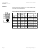
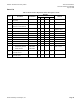
Table 11. Dimensions of the Actuator and Recommended Service Envelope.
Dimensions in Inches (Millimeters).
Actuator
Actuator
Prefix
Code
Actual
Height of
Actuator
H1
Service
Height
H
Actual Width or
Diameter of Actuator
W1
Service
Width
W
4-inch
Pneumatic
268, 269
270
5-3/4
(146)
14
(350)
5-1/2 (137)
diameter
18
(450)
8-inch
Pneumatic
277, 278
283, 284
14-1/8
(359)
26
(660)
8-3/4 (222)
diameter
21
(533)
12-inch
Pneumatic
279, 285 17-7/8
(454)
30
(762)
15-1/8 (384)
diameter
27
(686)
SKB 289, 291 14-3/4
(375)
22-3/4
(578)
14×9 (335 ×228)
25
(635)
SKD 274, 275
276, 279
11-13/16
(300)
19-3/4
(500)
5 (127) Width
6-5/8 (169) Depth
14-1/2
(360)
SQX 271, 272
273
8-7/8
(226)
17 (430) 5-17/32 (140) Width
4-3/8 (111) Depth
13-1/2
(340)
El/Mech
with linkage
295, 296
297
11 (280) 22 (559) 5-3/4 (144) Width
8-7/8 (225) Depth
25-3/4
(654)
Rack and Pinion 298, 299
14-1/2
(368)
24
(622)
5 (127) width*
5-1/8 (131) depth
13-1/2
(334)