
User Guide


Technical Bulletin Flowrite™ 599 Series Valve and Actuator Assembly Selection
Document No. 155-304P25
May 21, 2008
Page 16 Siemens Building Technologies, Inc.
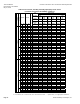
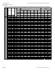
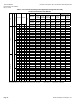
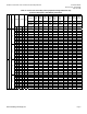
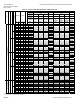
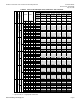
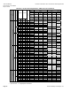
Table 5. 1/2 to 2-Inch Three-Way Valves (Equal Percentage NC/Linear NO)
(Technical Instructions 155-185P25).
Type Pneumatic
Pneumatic with Factory
Mounted Position Relay
Description
4-inch
3-8 psi
(21-55 kPa)
4-inch
5-10 psi
(34-69 kPa)
4-inch
10-15 psi
(69-103 kPa)
8-inch
8-inch
Hi-Temp
8-inch
8-inch
Hi-Temp
Technical
Instructions
155-183P25 155-183P25
155-183P25
155-161P25
155-161P25 155-161P25
155-161P25
Flow Rate Line Size
Actuator
Assembly
599-01081 599-01082 599-01083 599-01050 599-01051 599-01050 599-01051
Trim
Packing
Connection *
Cv Kvs In mm
Stroke
Valve
Assembly
Actuator
Code 268
Actuator
Code 269
Actuator
Code 270
Actuator
Code 277
Actuator
Code 278
Actuator
Code 283
Actuator
Code 284
1 0.9 0.5 15 20 599-03198 268-03198 269-03198 270-03198 277-03198 — 283-03198 —
1.6 1.4 0.5 15 20 599-03199 268-03199 269-03199 270-03199 277-03199 — 283-03199 —
2.5 2.2 0.5 15 20 599-03200 268-03200 269-03200 270-03200 277-03200 — 283-03200 —
4 3.4 0.5 15 20 599-03201 268-03201 269-03201 270-03201 277-03201 — 283-03201 —
6.3 5.4 0.75 20 20 599-03202 268-03202 269-03202 270-03202 277-03202 — 283-03202 —
10 8.6 1 25 20 599-03203 268-03203 269-03203 270-03203 277-03203 — 283-03203 —
16 14 1.25 32 20 599-03204 268-03204 269-03204 270-03204 277-03204 — 283-03204 —
25 22 1.5 40 20 599-03205 268-03205 269-03205 270-03205 277-03205 — 283-03205 —
FxF
40 34 2 50 20 599-03206 268-03206 269-03206 270-03206 277-03206 — 283-03206 —
1 0.9 0.5 15 20 599-03207 268-03207 269-03207 270-03207 277-03207 — 283-03207 —
1.6 1.4 0.5 15 20 599-03208 268-03208 269-03208 270-03208 277-03208 — 283-03208 —
2.5 2.2 0.5 15 20 599-03209 268-03209 269-03209 270-03209 277-03209 — 283-03209 —
4 3.4 0.5 15 20 599-03210 268-03210 269-03210 270-03210 277-03210 — 283-03210 —
6.3 5.4 0.75 20 20 599-03211 268-03211 269-03211 270-03211 277-03211 — 283-03211 —
10 8.6 1 25 20 599-03212 268-03212 269-03212 270-03212 277-03212 — 283-03212 —
16 14 1.25 32 20 599-03213 268-03213 269-03213 270-03213 277-03213 — 283-03213 —
25 22 1.5 40 20 599-03214 268-03214 269-03214 270-03214 277-03214 — 283-03214 —
Bronze
UFxUF
40 34 2 50 20 599-03215 268-03215 269-03215 270-03215 277-03215 — 283-03215 —
1 0.9 0.5 15 20 599-03144 268-03144 269-03144 270-03144 277-03144 — 283-03144 —
1.6 1.4 0.5 15 20 599-03145 268-03145 269-03145 270-03145 277-03145 — 283-03145 —
2.5 2.2 0.5 15 20 599-03146 268-03146 269-03146 270-03146 277-03146 — 283-03146 —
4 3.4 0.5 15 20 599-03147 268-03147 269-03147 270-03147 277-03147 — 283-03147 —
6.3 5.4 0.75 20 20 599-03148 268-03148 269-03148 270-03148 277-03148 — 283-03148 —
10 8.6 1 25 20 599-03149 268-03149 269-03149 270-03149 277-03149 — 283-03149 —
16 14 1.25 32 20 599-03150 268-03150 269-03150 270-03150 277-03150 — 283-03150 —
25 22 1.5 40 20 599-03151 268-03151 269-03151 270-03151 277-03151 — 283-03151 —
FxF
40 34 2 50 20 599-03152 268-03152 269-03152 270-03152 277-03152 — 283-03152 —
1 0.9 0.5 15 20 599-03153 268-03153 269-03153 270-03153 277-03153 — 283-03153 —
1.6 1.4 0.5 15 20 599-03154 268-03154 269-03154 270-03154 277-03154 — 283-03154 —
2.5 2.2 0.5 15 20 599-03155 268-03155 269-03155 270-03155 277-03155 — 283-03155 —
4 3.4 0.5 15 20 599-03156 268-03156 269-03156 270-03156 277-03156 — 283-03156 —
6.3 5.4 0.75 20 20 599-03157 268-03157 269-03157 270-03157 277-03157 — 283-03157 —
10 8.6 1 25 20 599-03158 268-03158 269-03158 270-03158 277-03158 — 283-03158 —
16 14 1.25 32 20 599-03159 268-03159 269-03159 270-03159 277-03159 — 283-03159 —
25 22 1.5 40 20 599-03160 268-03160 269-03160 270-03160 277-03160 — 283-03160 —
Stailness Steel
Standard
UFxUF
40 34 2 50 20 599-03161 268-03161 269-03161 270-03161 277-03161 — 283-03161 —
* F = Female NPT, UF = Union Female, UM = Union Male connection, — = Special Order, X = Inappropriate combination.