Technical Instructions Document No. 155-184P25 VF 599-3 July 23, 2008 Flowrite™ 599 Series Two-Way Valves 1/2 to 2-inch Bronze Body Description The Flowrite 599 Series two-way valves are designed to work with either a pneumatic or electronic actuator with a 3/4-inch (20 mm) stroke. They are available in ANSI Class 250 for normally closed or normally open action.
Technical Instructions Document Number 155-184P25 July 23, 2008 Specifications Flowrite 599 Series Two-Way Valves Line size Capacity Material Body style Seat style Action Stem travel (stroke) Valve body rating Body Body trim Stem Packing Normal duty packing Steam packing Operating Controlled medium 1/2 to 2 inches (15 to 50 mm) See Tables 3 through 6 and Figure 3 Globe style control valve with four connection options See Tables 1 and 2 Single seat, metal-to-metal Normally Closed (NC) Normally Open (N
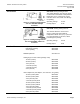
Flowrite 599 Series Two-Way Valves Technical Instructions Document Number 155-184P25 July 23, 2008 599-00417 Packing heating element. Accessories The heater allows the stem to move freely in valves that control fluids at temperatures below 32°F (0°C). It reduces ice crystal formation on the stem, which can damage the packing. Figure 1. Packing Heating Element For Use with SKD and SQX Actuators. Operating Voltage 24 Vac Heating Output 20 W 599-00418: Packing heating element.
Technical Instructions Document Number 155-184P25 July 23, 2008 Female NPT x Female NPT FxF Flowrite 599 Series Two-Way Valves Female NPT x Union Female FxUF Female NPT x Union Male FxUM Union Female x Union Female UFxUF Table 1. Normally Closed Valves. Flow Rate Cv (Kvs) Inch 1 (0.85) 1/2 1.6 2.5 4 6.3 10 16 Page 4 (1.37) (2.15) (3.44) (5.43) (8.6) (13.8) Equal Percentage Connection Stl.
Flowrite 599 Series Two-Way Valves Female NPT x Female NPT FxF Technical Instructions Document Number 155-184P25 July 23, 2008 Female NPT x Union Female FxUF Female NPT x Union Male FxUM Union Female x Union Female UFxUF Table 2. Normally Open Valves. Flow Rate Nominal Line Size Cv (Kvs) inch (mm) 1 (0.85) 1/2 (15) 1.6 (1.37) 1/2 (15) 2.5 (2.15) 1/2 (15) 4 (3.44) 1/2 (15) 6.3 (5.43) 3/4 (20) 10 (8.6) 1 (25) 16 (13.8) 1-1/4 (32) 25 (21.5) 1-1/2 (40) 40 (34.
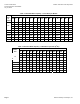
Technical Instructions Document Number 155-184P25 July 23, 2008 Flowrite 599 Series Two-Way Valves Table 3. Maximum Water Capacity - U.S. Gallons per Minute. Valve Size in Cv\1 2 inches 1.0 1.4 Pressure Differential - psi 3 4 5 6 8 10 15 20 25 30 40 50 60 75 1.7 2.0 2.2 2.5 2.8 3.2 3.9 4.5 5.0 5.5 6.3 7.1 7.8 8.7 8.0 1.6 2.3 2.8 3.2 3.6 3.9 4.5 5.1 6.2 7.2 8.8 10.1 11.3 12.4 13.9 2.5 3.5 4.3 5.0 5.6 6.1 7.1 7.9 97 11.2 12.5 13.7 15.8 17.7 19.
Flowrite 599 Series Two-Way Valves Technical Instructions Document Number 155-184P25 July 23, 2008 Table 5. Steam Capacity - Pounds per Hour. 3 4 5 6 8 10 9 12 Inlet Pressure - psig 50 25 Pressure Differential - psi 15 5 15 20 15 30 32.5 20 12.0 16.6 22 25 28 34 38 42 45 50 54 41 65 19.
Technical Instructions Document Number 155-184P25 July 23, 2008 Flowrite 599 Series Two-Way Valves Table 7. Body Temperature-Pressure Rating.
Flowrite 599 Series Two-Way Valves Technical Instructions Document Number 155-184P25 July 23, 2008 Table 8. Maximum Available Close-off Pressures for Pneumatic Actuators, Action, Upper Port.
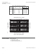
Technical Instructions Document Number 155-184P25 July 23, 2008 Flowrite 599 Series Two-Way Valves ELECTRONIC PNEUMATIC 1400 1200 150 1000 800 100 600 50 400 25 200 0 Differential Pressure (psi) 200 Differential Pressure (kPa) 3/4" 1" 1-1/4" 1-1/2" 1400 1200 150 1000 800 100 600 50 400 25 200 0 0 0 1/2" 1600 200 2" 1/2" 3/4" Line Size (in) 2" 200 1400 1200 150 1000 800 100 600 400 50 200 25 0 0 1/2" 3/4" 1" 1-1/4" 1-1/2" 2" Differential Pressure (psi) 250 1
Flowrite 599 Series Two-Way Valves Sizing Technical Instructions Document Number 155-184P25 July 23, 2008 The sizing of a valve is important for correct system operation. An undersized valve will not have sufficient capacity at maximum load. An oversized valve can initiate cycling and the seat and throttling plug can be damaged because of the restricted opening. Correct sizing of the control valve for actual expected conditions is considered essential for good control.
Technical Instructions Document Number 155-184P25 July 23, 2008 Flowrite 599 Series Two-Way Valves Dimensions The letters in Figure 6 refer to actuator and service envelope dimensions in Table 11. See Table 12 for valve body dimensions. Table 11. Dimensions of the Actuator and Recommended Service Envelope. Dimensions in Inches (Millimeters). Actuator 4-inch Pneumatic 8-inch Pneumatic 12-inch Pneumatic SKB Figure 6. Dimensions.
Flowrite 599 Series Two-Way Valves Technical Instructions Document Number 155-184P25 July 23, 2008 Dimensions, Continued Female NPT by Female NPT FxF Female NPT x Union Female FxUF Female NPT x Union Male FxUM Union Female x Union Female UFxUF Table 12. 2-Way Valve Dimensions in Inches (Millimeters).
Technical Instructions Document Number 155-184P25 July 23, 2008 Flowrite 599 Series Two-Way Valves Figure 7. Normally Closed 1/2-inch to 2-inch (15 to 50 mm) Line Size Valve. 1/2-inch (15 mm) Line Size Valve 3/4-inch to 2-inch (20 to 50 mm) Line Size Valve Figure 8. Normally Open. Page 14 Siemens Building Technologies, Inc.
Flowrite 599 Series Two-Way Valves Technical Instructions Document Number 155-184P25 July 23, 2008 Parts List Table 13. Parts List for 2-Way Bronze Valves. See Figures 7 and 8.
Technical Instructions Document Number 155-184P25 July 23, 2008 Flowrite 599 Series Two-Way Valves Valve Assembly Weight Page 16 Table 14. Weight in Pounds (Kilograms). Normally Closed FxUF FxUM UFxUF FxF Normally Open FxUF FxUM 4 (1.8) — — 3 (1.4) 3 (1.4) 3 (1.4) — — 4 (1.8) 5 (2.3) — — 4 (1.8) 4 (1.8) 5 (2.3) — — 5 (2.3) 5 (2.3) 5 (2.3) — — 5 (2.3) 6 (2.7) 6 (2.7) — — 1.25 (32) 7 (3.2) — — — — 9 (4.1) 7 (3.2) — — 8 (3.6) 9 (4.1) 1.50 (40) 8 (3.
Flowrite 599 Series Two-Way Valves Service Kit NOTE: Technical Instructions Document Number 155-184P25 July 23, 2008 To select the service kit, know your valve body assembly number, model number and the type of connection. Read down the Connection column until you find the valve body assembly number and then read to the far right to identify the correct kit. The valve body assembly number and model number are stamped on the tag on the valve body. Table 15. Rebuild/Repack Service Kits Part Numbers.
Technical Instructions Document Number 155-184P25 July 23, 2008 Flowrite 599 Series Two-Way Valves Service Kits, Continued Table 16. Rebuild/Repack Service Kits Part Numbers Continued. See Table 13 for Items in Kit. FxF Connection FxUF UFxUF FxUM Valve Description Model 1 Kit No. Model 2 Kit No. 599-03108 599-03117 — 599-03252 NO 1/2" =% SS 1.0 Cv O-ring 599-03336 — 599-03109 599-03118 — 599-03253 NO 1/2" =% SS 1.6 Cv O-ring 599-03337 — 599-03110 599-03119 — 599-03254 NO 1/2" =% SS 2.